Humanoid Robotics Electrical and Electronic Architecture
Why system architecture, not intelligence, decides whether humanoids scale
Humanoid robots concentrate more actuation, sensing, and compute per kilogram than almost any other engineered system. They are mobile, contact-rich, power-constrained, and expected to operate safely around humans while continuously evolving through software updates. In this regime, electrical and electronic architecture is not a background discipline. It is the structure that determines whether intelligence survives contact with physics, faults, and time.
This white paper examines humanoid EE architecture through a deliberate comparison with automotive E/E systems. Automotive experience provides invaluable discipline around safety, diagnostics, lifecycle governance, and scaling. At the same time, humanoids violate many of the assumptions that make automotive architectures work: sparse actuation, slow mechanical dynamics, predictable environments, and generous timing slack. The result is a domain where borrowed patterns must be adapted, constrained, or explicitly rejected.
The central argument is simple. Humanoid EE architecture must be designed around containment rather than convenience. Containment of timing jitter, of power transients, of faults, and of updates. Architectures that optimize early integration speed tend to accumulate hidden coupling that only surfaces under peak load, contact, or aging. Architectures that scale are those that encode their limits directly into hardware boundaries, timing contracts, and authority paths.
Context and system boundaries
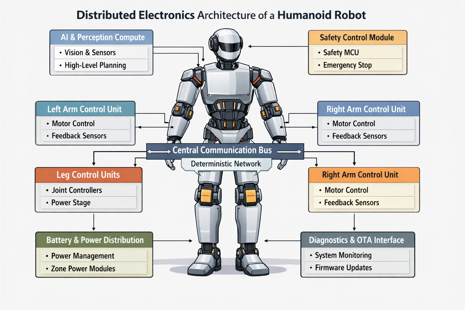
A humanoid robot is not a stationary machine with a single control cabinet. It is a distributed, human-scale system with dozens to more than a hundred actuators, dense sensing, high-bandwidth perception, and continuous physical interaction. Its EE architecture spans the full body: head, torso, arms, legs, and hands, all in motion, all electrically active.
From a system perspective, humanoid EE architecture must simultaneously support three fundamentally different domains. The first is hard real-time control for balance, locomotion, and force interaction, with loop rates typically between 500 Hz and 2 kHz and end-to-end latency budgets measured in milliseconds. The second is high-performance compute for perception, world modeling, and planning, characterized by bursty workloads, high power density, and weak real-time guarantees. The third is safety and supervision, which must remain authoritative under partial failure, power anomalies, or software faults.
Automotive E/E systems face a similar separation in principle. The difference is compression. Humanoids compress these domains into a far smaller volume, with higher actuator density, tighter mechanical-electrical coupling, and far less environmental predictability. This compression is what turns EE architecture from an optimization problem into a feasibility constraint.
The scope here includes compute placement, power distribution philosophy, communication fabrics, time synchronization, safety islands, diagnostics, and OTA boundaries. It explicitly excludes PCB-level design, inverter topologies, and application software beyond what constrains electrical partitioning. Fixing these boundaries early avoids a common failure mode where architectural debates collapse into component arguments while systemic risks remain untouched.
Humanoid versus automotive EE architecture boundaries
The value of automotive comparison lies in exposing silent assumptions. Automotive E/E systems evolved around predictable kinematics, limited actuator counts, and tightly bounded operating envelopes. Humanoids inherit some of the resulting discipline, but violate many of the premises that allow automotive architectures to scale cleanly.
| Dimension | Automotive E/E systems | Humanoid robotics EE systems |
|---|---|---|
| Actuator density | Tens of actuators, mostly low bandwidth | Dozens to >100 actuators, many torque-controlled |
| Real-time criticality | Safety-critical but often slow dynamics | Millisecond-scale balance and contact loops |
| Compute topology | Zonal or centralized | Necessarily hybrid with local control |
| Power distribution | High-voltage backbone, stable loads | Highly dynamic, motion-coupled loads |
| Safety concept | Fail-operational driving modes | Fail-safe, graceful degradation under contact |
| Environment | Well-bounded | Unstructured, human environments |
| Update strategy | OTA with homologation gates | OTA plus continuous adaptation |
This comparison clarifies why naïve reuse of automotive zonal architectures often fails in humanoids. Centralization simplifies wiring and lifecycle management, but pushes latency, fault propagation, and power transients into regimes that directly threaten balance and safe motion. Pure distribution improves control fidelity but explodes integration, diagnostics, and update risk. Viable humanoid architectures sit deliberately between these extremes.
Quantitative constraints that shape architecture
Humanoid EE architecture is bounded by physics, not intent. The numbers below are indicative, but they anchor feasibility.
| Constraint class | Typical range | Architectural implication |
|---|---|---|
| Joint control loop rate | 500 Hz – 2 kHz | Local control compute near actuators |
| End-to-end control latency | 1 – 5 ms | Strict separation from AI workloads |
| Safety reaction time | < 10 ms | Independent safety authority required |
| Peak electrical power | 3×–10× average | Power zoning and decoupling dominate |
| Compute power density | 5–15 W/cm² | Thermal limits constrain centralization |
| Actuator count | 30 – 120+ | Wiring and diagnostics scale nonlinearly |
| OTA cadence | Weeks to months | Hard update boundaries mandatory |
| Service interval | 6–24 months | Modular zones required |
These constraints explain why humanoid systems fail at interfaces. Latency budgets are consumed by network hops. Safety reaction times are exceeded by shared compute overload. Power transients destabilize sensing. Architecture must be shaped around worst-case behavior, not nominal demos.
Power distribution and grounding as architectural primitives
Power architecture is the least glamorous and most decisive part of a humanoid EE system. Whole-body motion creates rapid, correlated current spikes. A step, push recovery, or dual-arm manipulation can load dozens of actuators simultaneously, causing voltage droop, ground bounce, and EMI.
This pushes viable designs toward hierarchical power zoning. A primary energy source feeds multiple regional zones. Each zone performs local conversion, regulation, filtering, and fault isolation close to its actuators and sensors. Centralized low-voltage distribution almost always collapses under peak load as actuator count grows.
Grounding and isolation are equally architectural. High dI/dt motor drives, sensitive analog sensing, and high-speed digital links demand deliberate separation of power ground, signal reference, and safety earth where applicable. Automotive grounding heuristics help, but humanoids amplify the consequences of mistakes through tighter coupling and continuous contact.
From a safety standpoint, power architecture must support rapid energy removal. Hardware-level enable lines, zone-level power gating, and discharge paths must operate independently of high-level software. A humanoid that cannot reliably remove torque under fault conditions will not pass real-world scrutiny.
Compute domain partitioning and placement
The core EE mistake in humanoids is treating compute as a homogeneous resource. In reality, at least three incompatible compute domains are required.
The real-time control domain runs joint and body control loops. It demands deterministic execution, bounded interrupt latency, and direct sensor and actuator access. This domain typically lives on MCUs or real-time SoCs near limbs or joints. Sharing it with non-deterministic workloads is a primary cause of unexplained instability.
The AI and perception domain handles vision, mapping, and planning. It is throughput-optimized, power-hungry, and tolerant of variable latency. Centralization simplifies data handling but must be electrically and temporally isolated from control. Any architecture that allows AI load spikes to influence servo timing is fundamentally unsound.
The safety and supervision domain exists to enforce authority, not intelligence. It monitors timing, power, communication health, and motion envelopes, and must be able to intervene within guaranteed reaction times. Automotive safety MCUs are a strong reference, but humanoids often require tighter coupling to actuators and faster escalation paths.
The challenge is not defining these domains. It is enforcing their separation over years of updates and revisions. Successful humanoid platforms encode partitioning in hardware, not in process.
Communication, time, and the reality of partition
In humanoids, communication is part of the control system. Missed deadlines translate directly into physical instability. Architectures must therefore define traffic classes with explicit timing contracts.
A practical stack separates hard real-time actuator traffic, high-bandwidth perception traffic, and lifecycle traffic such as logs and OTA. Mixing these without strict QoS creates intermittent failures that are nearly impossible to reproduce.
Time synchronization is the enabling condition for distributed control. Without robust time authority and health metrics, latency compensation becomes guesswork. A common pattern is to define local deterministic islands for limbs, each capable of short-horizon stability, connected by a backbone used only for bounded traffic classes.
Fault containment and degraded operation
Humanoid networks rarely fail cleanly. They degrade through jitter, micro-outages, sync drift, and congestion. Architecture must treat these as normal conditions, not exceptions.
A degraded-mode ladder encodes predictable behavior under stress.
Mode 0 Normal operation supports full behavior and perception.
Mode 1 Constrained operation freezes high-risk behaviors, prioritizes control traffic, and reduces gains.
Mode 2 Safe-hold transitions to stable postures using local control islands.
Mode 3 Torque-off removes energy using hardware authority.
Each step down the ladder must reduce dependency on shared infrastructure.
| Failure mode | Symptom | Root cause | Mitigation |
|---|---|---|---|
| Latency jitter | Oscillation | Congestion | Constrained mode, QoS enforcement |
| Micro-outages | Torque steps | EMI, connectors | Safe-hold, local stabilization |
| Backbone partition | Loss of coordination | Switch failure | Island containment, torque limits |
| Time drift | Fusion errors | Sync loss | Local clocks, reduced coupling |
| OTA interference | Rare falls | Shared bandwidth | Hard update gating |
Reference humanoid EE architecture blueprint
A deployable humanoid EE architecture consists of three compute domains and hierarchical power zones.
A torso-mounted AI compute cluster handles perception and planning and is explicitly excluded from servo timing paths. Distributed real-time control islands reside in limbs and torso, capable of maintaining short-horizon stability independently. One or more safety islands hold direct authority over actuator enables and zone power gating.
Power is distributed through zone power modules per body region, each providing conversion, sensing, filtering, and fault isolation. Communication fabrics are separated into deterministic control, high-bandwidth perception, and lifecycle channels. Authority wiring such as e-stop chains and safety heartbeats bypass best-effort networks entirely.
Deployment gates that decide scale
A humanoid EE architecture is deployable only if it passes explicit gates.
Safety authority must be physically enforceable without AI or shared networks.
Timing closure must be proven under worst-case load, not nominal conditions.
Fault containment must yield bounded loss of capability.
Power integrity must survive motion peaks without corrupting sensing.
Serviceability must be modular and diagnosable.
OTA must not erode safety or timing guarantees.
Evidence generation must survive faults, not depend on them.
If these gates cannot be satisfied with measured evidence, the architecture is incomplete.
Why EE architecture decides the future of humanoids
Humanoid robotics is not constrained by algorithms alone. It is constrained by timing, power, fault behavior, and lifecycle discipline. Automotive E/E experience shows what happens when these are taken seriously. Humanoids amplify the consequences of ignoring them.
Architectures that encode containment, authority, and update boundaries will scale. Architectures that defer them will rediscover the same failures, only with better demos.
Intelligence only matters when it survives contact with reality.
Standards and compliance anchors relevant to humanoid EE architecture
These are not exhaustive checklists. They are anchor points that shape architectural decisions early, even when formal certification is still years away.
-
IEC 61508 (Functional Safety of E/E/PE Systems)
Establishes the foundational concepts of safety lifecycle, safety integrity levels, and independence. Humanoid safety islands and authority separation map naturally to these principles. -
ISO 10218 / ISO 13849 (Industrial robot safety)
While written for industrial robots, these standards influence expectations around safe torque off, emergency stop behavior, and safety-related control functions that humanoids must at least match or exceed. -
IEC 60204-1 (Safety of machinery – Electrical equipment)
Drives requirements around power isolation, grounding, emergency stop circuits, and fault behavior at the electrical level. -
ISO 21434 (Road vehicle cybersecurity)
Automotive-focused, but increasingly relevant for OTA, secure boot, update authorization, and threat modeling in mobile robots. -
IEC 62443 (Industrial cybersecurity)
Useful reference for network segmentation, zones and conduits, and defense-in-depth applied to robotic EE architectures.
The key architectural takeaway is that compliance is not “added later.” Safety authority, update boundaries, diagnostics, and segregation must exist in hardware and topology, or no amount of documentation will compensate.
Glossary and abbreviations
Glossary
-
Control island
A physically and logically bounded subsystem capable of maintaining safe, stable behavior independently for a limited time. -
Safety island
A compute and electrical domain with independent authority to enforce safe states, including torque removal and power gating. -
Degraded-mode ladder
A predefined sequence of reduced-capability states that the system transitions through under fault or stress conditions. -
Timing closure
Demonstrated proof that all real-time deadlines are met under worst-case load and fault conditions. -
Power zoning
Architectural partitioning of power distribution into independently protected and monitored regions. -
Fault containment
The ability to limit the impact of a fault to a bounded part of the system with predictable behavior.
Abbreviations
-
EE – Electrical and Electronic
-
MCU – Microcontroller Unit
-
OTA – Over-the-Air update
-
EMI – Electromagnetic Interference
-
QoS – Quality of Service
-
PTP – Precision Time Protocol
-
STO – Safe Torque Off