Technical Article
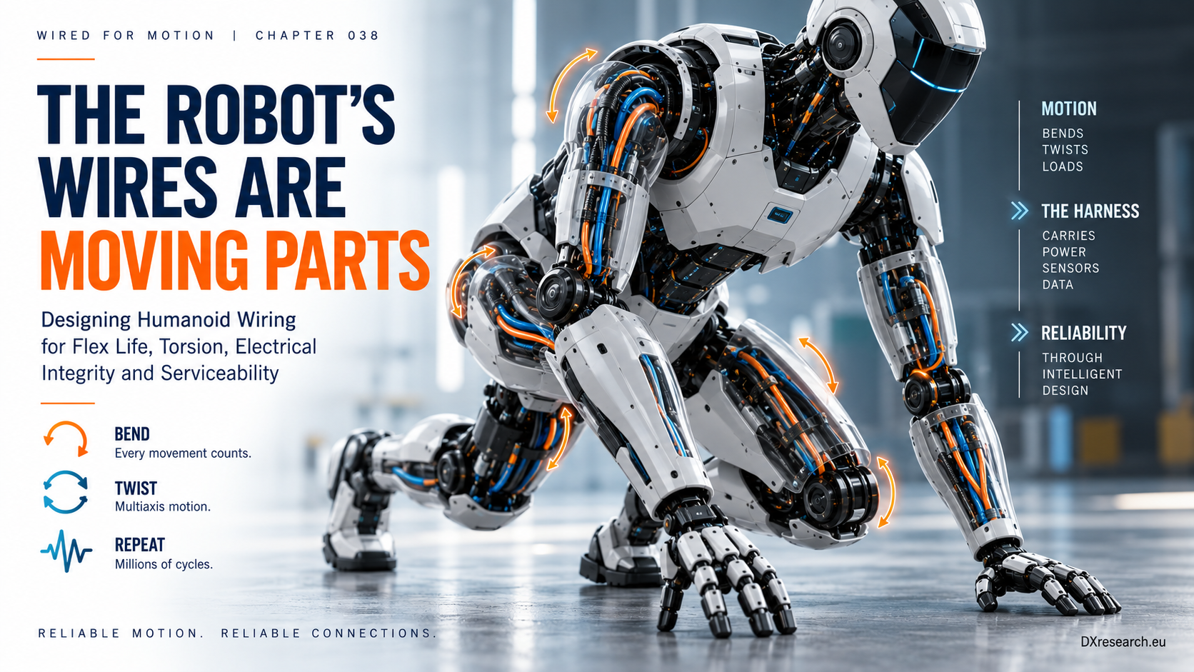
Wires Are Moving Parts
Designing Humanoid Wiring for Flex Life, Torsion, Electrical Integrity and Serviceability
Humanoid wiring moves with every joint, making flex life, torsion, routing, connectors, electrical integrity, diagnostics, and serviceability fundamental reliability requirements.
The harness has a motion profile
Electrical design normally begins with voltage, current, bandwidth, impedance and electromagnetic compatibility. A moving robot adds another set of requirements: bend radius, torsion, cycle count, strain concentration, connector motion and service access. IEC 60228 defines conductor construction and includes flexible copper conductor classes, but conductor flexibility alone does not prove that a finished cable is qualified for repeated robotic torsion or millions of dynamic cycles. IEC 60228:2023 A dynamic bend radius should be derived from the actual joint trajectory and routing geometry. The shoulder may combine bending and torsion; an elbow may impose repeated bending; a wrist can produce severe multidirectional rotation; and the torso may be comparatively static. The same cable construction should not be assumed suitable for every location.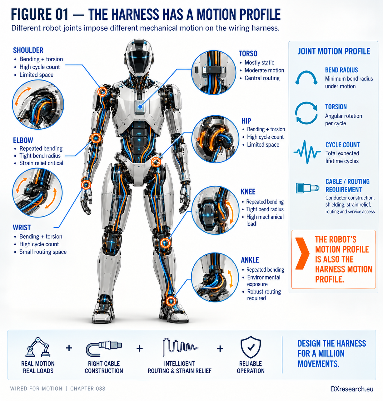
Flexible is not the same as robot-qualified
Robotics cable manufacturers distinguish ordinary flexible cable from constructions designed for repeated multidimensional motion. igus, for example, markets dedicated robot cables and torsion-qualified bus cables for articulated applications. igus robotic cable guidance A 2026 product announcement describes a DeviceNet cable rated by the manufacturer for ±360 degrees per metre torsion. igus torsion cable example Such values are company specifications for particular constructions, not universal limits. The relevant system quantity is flex life under the robot’s defined motion and environment. Conductor stranding, insulation, shield construction, jacket, temperature, routing, clamps and terminations all contribute. A cable that survives a laboratory bend test can still fail early if installed with an undersized radius or if torsion is concentrated beside a rigid connector.Failure starts before the wire opens
Repeated bending and torsion can fatigue conductor strands, disturb shields, wear insulation and concentrate stress near terminations. Connectors add their own mechanics: retention, fretting, contact resistance and strain transfer. TE Connectivity’s compact locking interconnects illustrate why connector retention and packaging are explicit robotics design concerns rather than afterthoughts. TE Connectivity connector example Strain relief should keep motion away from sensitive terminations, while a harness service loop can provide controlled movement and maintenance allowance. Neither is free: excess cable consumes space and can rub or snag, while excessive constraint localizes strain. Importantly, mechanical degradation can create electrical symptoms before complete failure. Increasing resistance can produce voltage drop. Intermittent contacts can appear as communication errors, node resets or sensor discontinuities. Shield degradation can alter EMC behavior. These observations create a path toward interconnect health monitoring, although not every degradation mechanism is continuously observable.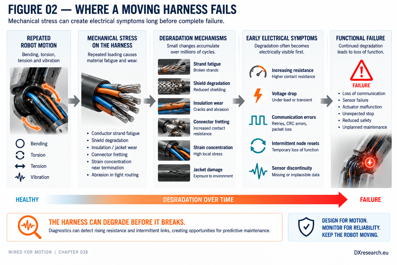
Connector mechanics belong in the reliability budget
A humanoid may contain many removable joints, sensors and distributed controllers. Every connector improves assembly or serviceability but also creates contacts, retention mechanisms and transition regions that must survive vibration and motion. Connector retention therefore belongs in the same reliability discussion as conductor fatigue. Service strategy changes the optimum. A permanently routed harness can minimize connectors but make replacement expensive. Modular limb harnesses can improve repair time but add interfaces. The correct design depends on mission profile, expected maintenance, access, contamination, motion and acceptable downtime.Architecture determines what crosses the joint
Semiconductor placement changes harness topology. A centralized architecture can require long sensor, actuator and communication runs across several moving joints. Distributed electronics can place sensing, processing, motor control or power conversion closer to the load, reducing some long raw-signal or high-current paths. But decentralization also adds local electronics, connectors, thermal sources and service points. The useful question is therefore not whether distributed electronics are universally better. It is which electrical functions should cross each joint and in what form. A shared data backbone can replace multiple raw sensor wires; local motor control can shorten phase or feedback paths; local conversion can change current levels. Each choice transfers complexity between cable, connector, semiconductor, thermal and software domains.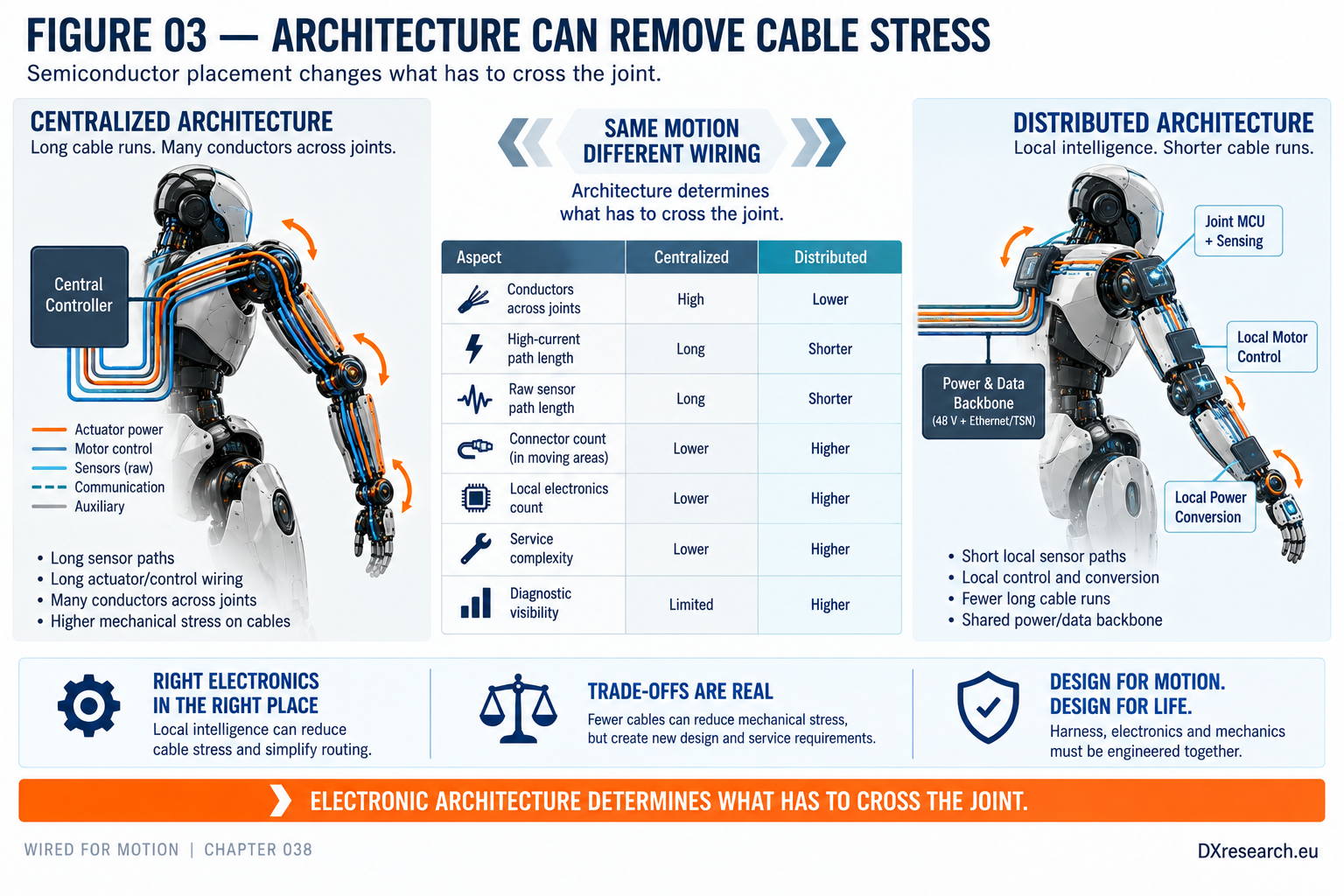
Design the harness from the motion inward
A robust workflow begins with joint kinematics and mission profile, not with a cable catalogue. Map the movement at each routing zone. Define the electrical load and data requirement. Establish bend, torsion, thermal and environmental boundaries. Select cable and connector constructions against those conditions. Then validate the installed harness through representative motion rather than treating component qualification as system qualification. The long-term opportunity is a robot that understands parts of its own interconnect condition. Voltage-drop trends, resistance measurements, communication-error counters and intermittent-reset histories can provide evidence for maintenance decisions when interpreted carefully. This is an architectural extrapolation, not yet a universal humanoid standard. The central principle is simple: the wires move too. A humanoid cannot achieve automotive-like reliability by engineering joints for millions of movements while treating the electrical nervous system crossing those joints as static infrastructure. Motion, electronics, diagnostics and serviceability have to be designed as one system.Glossary
- Connector retention
- Mechanical means used to keep a connector securely mated under vibration, movement and service loads.
- Dynamic bend radius
- Minimum bend radius specified for a cable while it is repeatedly moving rather than remaining statically installed.
- Flex life
- Expected endurance of a cable or interconnect under a defined repeated-motion profile before specified degradation or failure criteria are reached.
- Harness service loop
- Deliberate cable-length and routing allowance that accommodates articulation, assembly or maintenance without excessive local strain.
- Interconnect health
- Condition of conductors, contacts, shields and terminations inferred from electrical, communication or inspection evidence.
- Strain relief
- Mechanical feature that limits transfer of tensile, bending or torsional loads into an electrical termination.
- Torsion rating
- Manufacturer-defined rotational deformation capability of a cable under specified length, cycle and environmental conditions.
Sources
- Dynamic D-1000 Slim Connector · TE Connectivity
Compact locking interconnect example relevant to dense robotics, servo-motor and sensor applications where retention and service access matter.
https://www.te.com/ - IEC 60228:2023 — Conductors of insulated cables · 2023-12-11 · International Electrotechnical Commission
Defines nominal cross-sections, construction and resistance requirements for conductors in electric cables, including classes of flexible copper conductors.
https://webstore.iec.ch/en/publication/72675 - Robotic Cables for Multi-Axis Robots & Dress Packs · igus
Manufacturer guidance and product evidence for cables engineered for repeated multidimensional robotic bending and torsional motion.
https://www.igus.com/chainflex/robot-cables - Using DeviceNet safely: new chainflex bus cable for ±360°/m torsion on robots · 2026-07-30 · igus
Manufacturer example of a robot bus cable designed and qualified for substantial repeated torsional motion; numerical capability remains product-specific.
https://press.igus.eu/