
Technical Paper / IEEE-style
Motors
Motor technologies, integrated actuation and semiconductor pathways for scalable humanoid robots
Humanoid body joints are converging on permanent-magnet synchronous machines, yet scale will be determined by the complete actuator. Present architectures and emerging conductors, magnet-free machines, integrated sensing and smart-joint electronics are compared against mission-level energy, industrialization constraints and semiconductor requirements across distinct body joints and production maturity horizons.
Abstract
Humanoid body joints are frequently discussed as a motor-selection problem. In practice, motor electromagnetic design, transmission ratio, sensing, cooling, inverter behavior, control bandwidth and mechanical integration form one inseparable energy and reliability system. Current commercial evidence points to three-phase permanent-magnet synchronous machines as the dominant body-joint motor. Their surrounding architectures are diverging into low-ratio quasi-direct drives, high-ratio rotary modules, screw-driven linear actuators and compliant mechanisms. Emerging options include carbon-based and aluminium conductors, printed stators, amorphous cores, electrically excited and reluctance machines, multiphase drives, sensorized gears and highly integrated smart joints. Patents and announcements provide directional evidence, not proof of production readiness. The near-term breakthrough is unlikely to be one universal motor; a small family of mission-profile-validated, sensorized and serviceable joint platforms is more plausible. This transition increases the role of power semiconductors, real-time control, precision sensing, deterministic communications, functional safety and condition monitoring while changing where value is created in the actuator.
1. Humanoid actuation has become a system problem
A humanoid can complete an impressive movement while its actuator architecture remains commercially unviable. The evidence appears later: a shoulder that reaches its thermal limit after repeated overhead handling; a knee reducer whose friction corrupts torque estimation; a harness connector loosened by impacts; a calibrated torque sensor that cannot be replaced without repeating an expensive end-of-line process. None of these failures is visible in a peak-torque specification. All of them determine whether the robot produces useful work.
The distinction between motor and actuator is therefore fundamental. The motor converts electrical power into shaft torque. The actuator must also convert speed, support load, measure position and force, reject heat, survive impacts, communicate deterministically, stop safely and remain maintainable. Its effective boundary includes the inverter, local controller, current sensors, rotor and output encoders, reducer or screw, bearings, brake, torque sensor, thermal path, housing, connectors and software parameters. Optimization of only one element can move loss or cost elsewhere without improving the robot.
Public product data provides a useful anchor. Unitree identifies the G1 joint motor as a low-inertia, high-speed, internal-rotor PMSM. The platform uses 23 to 43 joint motors, dual encoders and local air cooling; its largest knee specification is 90 or 120 N·m depending on configuration [1]. This is unusually explicit confirmation of an architecture that is widely inferred elsewhere. Figure states that it manufactures motors and actuators internally and that its Figure 03 actuators operate at twice the prior speed with improved torque density, but it does not publish motor topology [2], [3]. Apptronik describes a proprietary actuator platform designed for efficiency, maintainability and mass manufacture, while leaving the motor and transmission details undisclosed [4]. Boston Dynamics confirms that the current Atlas is fully electric, but similarly does not disclose the electromagnetic topology [5].
These disclosure boundaries matter. A visually plausible teardown, supplier rumor or recruitment description may indicate a direction, but it cannot support a definitive platform claim. Four evidence classes remain distinct: confirmed product fact; bounded company claim; patent or research disclosure; and engineering interpretation. A patent establishes that a configuration was conceived and claimed, not that it is used in a current robot. A company efficiency number remains incomplete unless operating point, measurement boundary, cooling state and duty cycle are known.
The central proposition is consequently narrower and stronger: PMSM technology is the present baseline, but the scalable competitive unit is becoming the smart joint. Motor innovation remains important; its value must be measured at joint and robot level.
2. Requirements differ across the body
The phrase “humanoid joint motor” hides several distinct duty classes. Hip pitch and knee axes combine high peak torque, substantial speed, impacts and regenerative intervals. Hip yaw and waist axes may spend longer periods producing static or slowly varying torque. Ankles require rapid bidirectional response and high contact sensitivity. Shoulders must deliver useful torque without imposing excessive mass on upstream joints. Elbows and wrists prioritize transparency, low inertia and smooth manipulation. Neck axes operate at low mechanical power but severe packaging constraints. One electromagnetic design cannot be optimal across all of them.
| Region | Dominant requirement | Likely actuator direction | Primary limiting mechanism |
|---|---|---|---|
| Hip pitch/roll | Peak torque, shock and regeneration | High-torque PMSM with low-to-medium ratio | Phase current and thermal cycling |
| Hip yaw/waist | Sustained moment and packaging | Geared frameless PMSM, brake or counterbalance | Holding loss and gear friction |
| Knee | Power, impact and repetitive cycling | QDD rotary or screw-driven linear actuator | Winding temperature, screw/reducer life |
| Ankle | Fast torque reversal and contact response | Backdrivable low-ratio PMSM | Control latency and reflected inertia |
| Shoulder | Torque density with low moving mass | Frameless PMSM with moderate reduction | Thermal path and distal mass |
| Elbow/wrist | Transparency and precision | Compact frameless, slotless or tendon drive | Cogging, backlash and packaging |
| Neck | Compact, quiet positioning | Small geared BLDC/PMSM | Noise and connector volume |
Motor sizing must therefore use torque–speed–time trajectories rather than a single nominal or peak point. Copper loss is approximately proportional to current squared. A short high-current event can be acceptable because the winding and housing absorb heat transiently. The same current repeated without sufficient recovery produces thermal accumulation. Conversely, a waist joint can overheat at zero speed even though mechanical output power is zero, because gravity compensation requires current continuously. A brake, latch, spring or counterweight may save more energy than a higher-efficiency inverter.
Mass location introduces another coupling. A gram removed from a wrist reduces wrist inertia, elbow load, shoulder load and, during whole-body motion, balance effort. A heavier high-torque motor may still improve total performance if it permits a lower gear ratio and reduces reflected inertia or friction. The correct objective is not motor torque density in isolation but mission-weighted joint performance, including the energy consequence of actuator mass at its body location.
Safety requirements also vary. Failure of a neck axis is usually manageable. Loss of knee torque during single support can create a fall. Industrial humanoids may therefore require redundant position information, safe torque off, controlled braking, fault-tolerant winding or inverter operation, and a defined degraded movement into a stable pose at selected load-bearing joints. Applying identical safety hardware to every axis would be costly; omitting differentiation would be unsafe.
3. Present motor and actuator baseline
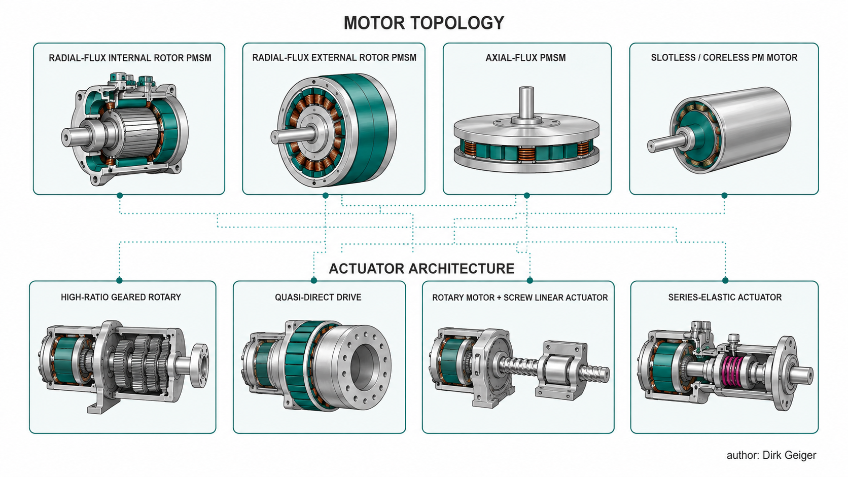
Three-phase radial-flux PMSMs dominate high-performance electric joint actuation. The rotor carries permanent magnets; the stator carries three-phase windings; an inverter applies controlled currents, normally through field-oriented control. Industry language often calls the same machine a BLDC motor. The distinction usually describes commutation and back-EMF assumptions rather than a completely different physical machine. For modern humanoid torque control, sinusoidal current regulation and rotor-position feedback make PMSM the more precise system term.
An internal rotor offers low rotor inertia, mechanically contained magnets and a straightforward external stator cooling path. The motor can run at relatively high speed and use a reducer to multiply torque. Unitree’s explicit G1 description supports this baseline [1]. An external rotor places the magnets on a larger radius and can generate greater torque for a given axial length, but it increases rotor inertia and complicates containment and integration. External-rotor machines can suit low-ratio drives where torque radius is valuable and rapid rotor acceleration is less dominant.
Frameless construction is particularly important. Supplying rotor and stator without duplicated bearings, shaft and housing allows the actuator structure to serve several functions. It supports hollow routing, shortens the torque path and reduces mass. Maxon’s ALLEX example combines an ultra-slim frameless motor with a proprietary low-friction reducer to improve backdrivability and reduce rotational inertia [6]. The example supports the integration principle, not a claim that the same design is used in full-body industrial humanoids.
Axial-flux PMSMs arrange magnetic flux largely parallel to the shaft. Their large active radius and flat geometry can suit shoulder roll, hip yaw, waist and other disc-shaped envelopes. They also create engineering challenges: tight axial air-gap control, rotor-disc stiffness, magnet retention, bearing load, double-sided thermal extraction and production tolerances. Axial flux is therefore a selectable packaging solution, not an inherently superior successor to radial flux.
Slotless or coreless PM motors reduce cogging and rotor–stator force ripple. Their smooth response can benefit wrists, necks and precision manipulation. They usually sacrifice continuous torque density or thermal conduction because less magnetic material and winding support occupy the active volume. Direct drive eliminates gearing and maximizes torque transparency, but a body-scale direct-drive motor is generally too large or heavy for the required continuous torque. Most systems use some reduction.
Alternative fundamental motor types remain uncommon in published humanoid body-joint evidence. Induction motors avoid rotor magnets but generally offer inferior torque and efficiency at the relevant scale. Synchronous- and switched-reluctance machines offer magnet-free rotors but impose power-factor, ripple, noise or control penalties. Brushed DC motors remain useful in low-cost miniature mechanisms, but brush wear and electrical noise conflict with long-life industrial body joints.
The public evidence does not justify assigning detailed topologies to Tesla, Figure, Atlas, Digit or Apollo. Tesla recruitment material does confirm engineering work on gear trains for rotary and linear Optimus actuator systems in coordination with electromagnetic motor teams [7]. This supports a mixed actuator architecture, but not a specific winding, rotor or screw configuration. Figure’s published manufacturing strategy confirms vertical integration of motors and actuators [2]. Atlas is confirmed electric [5]. Apptronik’s greater-than-90-percent actuator-efficiency statement is a company design claim without a published efficiency map [4].
4. Transmission, compliance and thermal behavior
The motor creates shaft torque; the transmission determines how that torque reaches the body. A high-ratio strain-wave reducer produces a compact joint with high output torque and precise positioning. It also reflects motor inertia through the square of ratio, introduces friction and hysteresis, and can make externally applied loads difficult to sense. Cycloidal reducers offer shock capacity and different stiffness characteristics but remain precision mechanical assemblies. Planetary stages can achieve high efficiency at modest ratios, supporting quasi-direct drive.
QDD architectures use a relatively large motor and a low reduction ratio. Their advantages are backdrivability, lower reflected inertia, effective regeneration and more transparent current-to-output-torque behavior. Their disadvantages are high phase current, larger active material volume and substantial heat generation during static torque. QDD shifts cost from precision gearing toward magnets, copper, power MOSFETs, current sensing, cooling and control.
A rotary-to-linear actuator uses a motor to drive a ball or planetary roller screw, creating force that acts through a linkage. The arrangement can produce high force density and place components efficiently around a knee or ankle. Its total efficiency depends on screw lead, preload, lubrication, seals, linkage geometry and load direction. Backdrivability may change across the mechanism’s travel. The label “linear actuator” should not be confused with a direct electromagnetic linear motor.
An SEA inserts a calibrated elastic element between motor/transmission and load. Spring deflection provides force information, absorbs impacts and improves stable force control. The cost is additional travel, phase lag, resonance and reduced high-frequency stiffness. The appropriate spring rate depends on the task: a leg that must survive foot strike differs from a wrist that must place a connector. Historic humanoid work, including NASA-related integrated torque-control developments, illustrates the long-standing movement toward local high-speed torque loops [8].
Thermal behavior unifies these mechanical choices. Motor copper loss, stator iron loss, inverter conduction and switching loss, bearing loss, gear friction, seal friction and brake loss all become heat within a limited envelope. Integrating the electronics shortens wiring but places temperature-sensitive capacitors, sensors and processors closer to windings and gears. A motor can have an efficient electromagnetic operating point while the actuator performs poorly because of reducer friction. A highly backdrivable actuator can reduce collision forces but consume more holding current.
Regeneration is similarly systemic. A knee may generate electrical power during lowering, but recovered energy only helps if the inverter allows bidirectional flow, the DC bus accepts it, another load consumes it or the battery and power path can absorb it. Otherwise the bus voltage rises and energy must be dissipated or regeneration curtailed. The robot needs coordinated energy management rather than independent motor controllers treating each joint as an isolated axis.
5. Scaling exposes different customer pain points
Prototype development rewards maximum capability. Series production rewards repeatability. Figure’s BotQ announcement describes an initial production line capacity of 12,000 humanoids per year and identifies part count, complex machining and long process time as barriers. The Figure 03 redesign moved toward tooling, stamping, die casting, metal injection molding and injection molding [2]. Those choices reveal an industrial truth: an actuator that is marginally lighter but requires several tightly toleranced CNC parts may lose to a slightly heavier unit built through stable, automated processes.
Actuation is also economically dominant. Schaeffler estimates that actuators represent about half the value of the bill of materials in many humanoids and positions motors, rotary and linear drives, sensors and electronics as an integrated production and lifecycle proposition [15]. The percentage varies by robot configuration and accounting boundary, but the strategic direction is robust. Every body degree of freedom multiplies motor, reducer, encoder, controller, connector, calibration and test cost.
| Pain point | Observed consequence | Preferred response |
|---|---|---|
| Rare-earth exposure | Price volatility and geographic concentration | Magnet reduction, alternative machines, recycling and dual sourcing |
| Thermal derating | Cycle time falls after repeated work | Loss maps, embedded sensing, cooling and mission-based sizing |
| Precision reducer cost | High BOM and long supplier lead time | Common sizes, lower ratios, design for automated assembly |
| Torque-sensor calibration | Expensive end-of-line equipment and drift | Sensorized structures, self-calibration and observer redundancy |
| Harness complexity | Assembly labor and intermittent faults | Local control, shared DC bus and deterministic serial network |
| Repair time | Low fleet availability | Replaceable sealed modules with retained calibration identity |
| Variant proliferation | Low purchasing scale and spare-part burden | Three to five joint families with software-configured limits |
| Insufficient evidence | Peak ratings fail to predict work capability | Standard torque-speed-thermal and mission-profile tests |
Holding energy is often underestimated. A motor can be 95 percent efficient at a rated moving point and still waste substantial energy while the robot stands, holds its arms forward or carries a load. Mechanical brakes, counterbalances, springs, variable-stiffness structures and posture planning can suppress current when motion is unnecessary. They may add mass and constraints, so their value must be evaluated across the mission.
Calibration is another hidden factory. Dual encoders need zero alignment; phase current sensors need offset and gain calibration; torque bridges require temperature compensation; motor parameters vary with manufacturing; gear friction changes during run-in. At thousands of robots per year, calibration stations, fixtures, traceability and retest time become production assets. The smart joint should carry a secure digital identity, calibration record and lifetime history.
Serviceability changes optimization. A fully integrated actuator reduces assembly count but can turn a small sensor failure into complete module replacement. The commercially effective boundary may therefore be a sealed line-replaceable joint with internal diagnosability and a planned remanufacturing route. Integration without health monitoring merely hides failure mechanisms.
6. Next-generation conductors and magnetic materials
6.1 Carbon-based windings
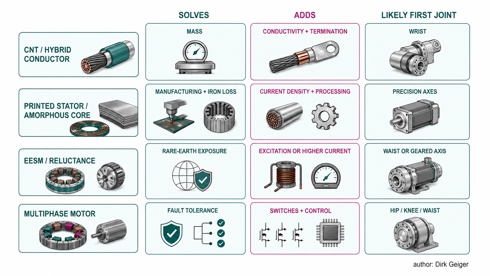
Carbon conductors are attractive because humanoids amplify distal mass. A lighter wrist winding reduces not only wrist inertia but also elbow and shoulder load. In April 2025, Ryu et al. reported continuous CNT wires in a flexible polymer sheath and demonstrated operation of a small motor and model vehicle [12]. The work is legitimate evidence of a functioning carbon-based winding. It is not evidence of a humanoid-ready body-joint motor.
The distinction is quantitative. The reported conductor conductivity was far below bulk copper, while its density was much lower. Specific conductivity can therefore appear favorable even when a conductor of equal length and cross-section has higher resistance. A high-current humanoid joint would need more cross-sectional area, higher voltage, a different winding geometry or acceptance of increased loss. Termination may become the dominant failure mechanism: CNT-to-busbar contact resistance, environmental sealing, impregnation, insulation and repeatable crimping or bonding all require industrial solutions.
The credible adoption path is staged. Copper-clad aluminium and improved aluminium terminations can address cost and weight first. CNT–copper or CNT–aluminium hybrids may improve specific properties without requiring an entirely new connector ecosystem. Pure CNT conductors could enter distal or intermittent-duty axes before knees and hips. The decision must include conductor mass, slot fill, resistance, thermal conductivity, joining, yield, repair and material cost—not a laboratory rotational-speed comparison alone.
Semiconductor implications follow from the winding. Higher resistance raises the value of low-conduction-loss MOSFETs and accurate winding-temperature estimation. Increasing bus voltage to reduce current changes device rating and insulation requirements. Online resistance identification can track temperature and detect degraded joints. Faster wide-bandgap switching offers limited benefit if winding loss dominates.
6.2 Printed and PCB stators
Printed stators replace inserted round wire or hairpins with repeatable planar copper geometry. In an axial-flux arrangement they can provide a thin form factor, low cogging and automated fabrication. The manufacturing appeal is strong: conductor location, phase geometry and sensor features are defined photolithographically rather than by a variable winding process. Motor and electronics can share a substrate or thermal interface.
The constraint is current density and heat extraction. A planar conductor may have less copper cross-section than a conventional slot and can develop concentrated losses at vias and interconnects. Printed stators are therefore more credible near-term for neck, wrist, gripper and high-speed geared axes than for sustained high-torque knees. Parallel board stacks, heavy copper and direct liquid or structural cooling can extend the range but add complexity.
For semiconductors, the topology creates a route to very short inverter-to-winding connections, low parasitic inductance and integrated current and temperature sensing. GaN can become attractive in compact high-frequency axes. The same fast edges increase common-mode current and electromagnetic compatibility demands. Partial discharge is less likely at low robot voltages, but insulation stress and bearing currents still require attention.
6.3 Amorphous and nanocrystalline cores
Conventional electrical steel is mature, strong and inexpensive. Amorphous alloys can reduce eddy-current and hysteresis losses at high electrical frequency. Proterial reports a prototype comparison in which an amorphous stator reduced iron loss to about one fifth, improved motor efficiency by more than three percentage points and halved thermal generation [13]. These values are company-reported for a specific motor and cannot be transferred directly to a humanoid joint.
The best humanoid case is a high-speed motor behind a reducer, particularly with high pole count or switching harmonics. Low iron loss permits greater speed or smaller thermal margin. Manufacturing is difficult because thin amorphous strip can be brittle, sensitive to cutting damage and harder to stack into three-dimensional teeth. The economic question is whether lower loss reduces motor size, cooling hardware or battery energy enough to pay for core processing.
Lower core loss also changes inverter optimization. Harmonic currents that were previously obscured by ordinary core loss become more visible. Precise PWM, dead-time compensation and current reconstruction gain importance. The motor and inverter must be measured together across switching frequency rather than optimized separately.
6.4 Structural and multi-axis machines
A further direction removes duplicated structure. The stator becomes part of the limb; the output bearing becomes the joint bearing; the inverter becomes an end cap; cooling channels are cast into the load path. Such integration can reduce parts and mass but increases thermomechanical coupling. Gear shock reaches the PCB, winding heat reaches the encoder, and replacing one element may require replacing the entire module.
True spherical or multi-axis motors promise to replace two or three single-axis joints with one electromagnetic machine. Patents demonstrate long-standing interest, but control, torque density, bearing design, magnetic cross-coupling and manufacturing remain unresolved for body-scale industrial use. Multi-axis machines should be considered a long-horizon architecture. Structural integration of conventional single-axis machines is the nearer opportunity.
7. Rare-earth-reduced and magnet-free machines
7.1 Electrically excited synchronous motors
An EESM replaces rotor permanent magnets with a wound field. The rotor flux becomes controllable and rare-earth magnets are eliminated. Automotive evidence establishes feasibility at scale: Renault states that it has mass-marketed EESM drives since 2012 [10]. ZF’s I²SM transfers excitation energy inductively within the rotor and removes brushes and slip rings [9]. Valeo and MAHLE announced an inner brushless excitation development combining rotor excitation, inverter expertise and contactless energy transfer [11]. These sources concern vehicle traction, not humanoid joints.
Transfer is not straightforward. A vehicle motor spends significant time rotating at power. A humanoid body joint often operates slowly, intermittently or at standstill. An EESM then pays stator copper loss and rotor excitation loss while self-cooling is weak. The exciter, rotor rectifier, field winding and additional control channel consume axial space and create new failure modes. In a compact knee, those penalties may outweigh magnet independence.
EESM nevertheless offers useful properties. Rotor field can be reduced in high-speed operation or a fault, lowering back-EMF. Magnet supply exposure and demagnetization risk disappear. Flux can be optimized across operating points. Larger waist, hip or shoulder modules may provide enough volume for an inductive exciter. A robot family designed for supply resilience or high-temperature operation could accept lower torque density.
The semiconductor content rises. In addition to the main three-phase inverter, the joint needs an excitation power stage, contactless coupling control, rotor rectification and field-current estimation. Safe shutdown must address both stator and field energy. An integrated controller must coordinate torque-producing current and excitation current while observing thermal limits. Magnet material is substituted partly by copper, magnetic components, switches and control software.
7.2 Synchronous reluctance and ferrite assistance
A SynRM produces torque from rotor saliency. Its rotor can avoid magnets and windings, improving robustness and material security. The penalties are reduced power factor, increased current for a given torque and often lower torque density. Ferrite-assisted designs add inexpensive, non-rare-earth magnets to improve flux and power factor. They may offer a practical compromise before fully magnet-free machines mature.
Humanoid relevance depends on system boundaries. Higher current increases winding and inverter mass, but a simple rotor can reduce cost and withstand temperature. A ferrite-assisted motor may suit a high-speed geared actuator where volume is available. For a QDD knee with severe diameter and current limits, NdFeB PMSM remains difficult to displace.
7.3 Switched reluctance and multiphase machines
An SRM uses a simple salient rotor and sequential stator excitation. It tolerates high temperature and can be fault tolerant. Torque ripple, acoustic noise and nonlinear control are major barriers for humanoids working near people. Increased phase count, current shaping and structural optimization can reduce these effects, but increase switch count and software complexity.
Multiphase PMSM or reluctance machines address a different requirement: controlled degradation. Two independent three-phase winding sets can retain limited torque after a phase, inverter or supply-domain failure. This may be valuable in hip, knee and waist axes where immediate torque loss creates a fall. It is unnecessary for every neck or finger axis. The correct safety architecture assigns redundancy according to hazard and stable-pose strategy.
More phases increase semiconductor count but can lower per-phase current and create two monitorable channels. Dual three-phase gate drivers, independent sensing, cross-monitoring MCUs and phase isolation become relevant. The design objective is not indefinite operation after failure; it is sufficient verified control to reach a safe mechanical state.
8. The smart joint becomes the product
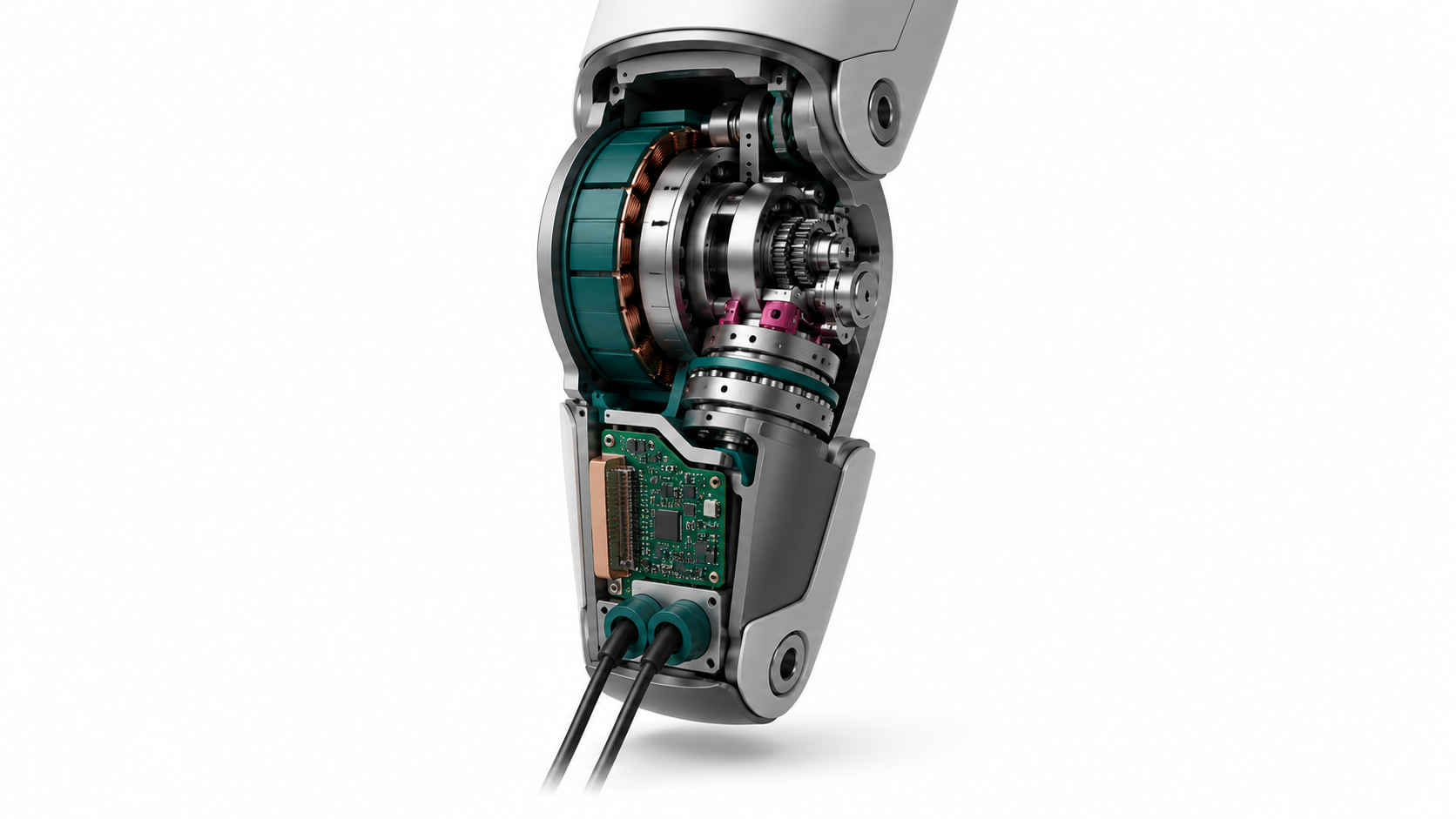
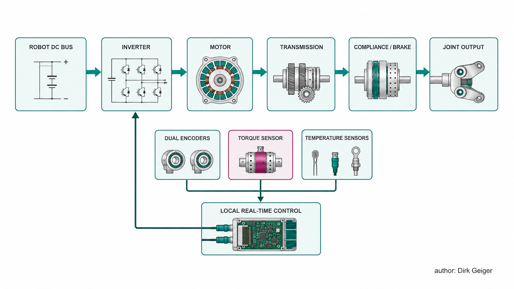
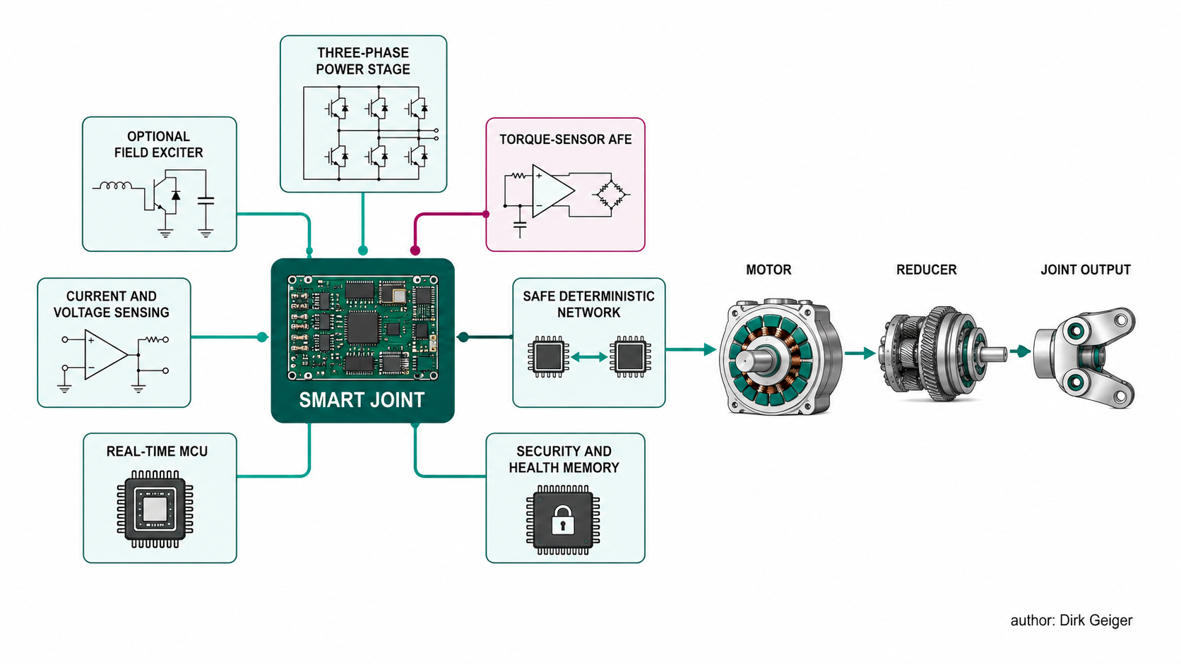
The most credible near-term innovation integrates a conventional high-performance motor with the rest of the actuator. The target module combines motor, reducer or screw, bearings, dual position sensing, output torque sensing, brake, inverter, real-time control, communications, temperature sensing and a secure calibration identity. It reduces the robot OEM’s task from assembling a mechatronic chain to configuring a qualified node.
The concept has historical depth. A 2011 published patent describes a collocated joint processor, inverter module, sensor-conditioning electronics and high-speed bus providing a local torque loop [8]. A Chinese patent published in 2025 describes a motor, strain-wave mechanism, integrated torque sensor, brake, magnetic position sensing and controller board in one joint module [14]. Neither patent proves present commercial adoption. Together they show continuity: local torque control has evolved into structural, sensing and service integration.
Integration creates measurable advantages. Phase leads shorten, reducing resistive loss and electromagnetic emissions. Encoder and torque signals avoid long analog paths. Cabling can collapse to DC power and a deterministic network. Factory assembly count falls. A common joint can be configured through current, torque, speed and thermal limits for several body positions. Firmware can implement local impedance, collision response and health estimation at higher bandwidth than a remote computer.
It also creates concentrated risks. The inverter shares the motor thermal environment. Lubricant vapor and gear debris can affect electronics. Vibration and foot-strike shock reach solder joints and magnetic sensors. A sealed housing traps heat. A firmware defect can affect a common joint family across the fleet. Cybersecurity becomes a physical-safety concern because a compromised node can generate torque.
A production smart joint therefore needs explicit partitions. The fast current loop and safety monitors remain local. Whole-body optimization and coordinated regeneration remain higher-level functions. Safety shutdown must not depend solely on application firmware. Secure boot, authenticated updates, rollback protection and per-device credentials protect fleet integrity. Calibration parameters must be versioned and bound to the physical module.
Standardization should not imply one size. Three to five torque-frame classes can cover distal precision, arm, shoulder/waist and leg loads. Common electronics, software, connectors and diagnostics create scale while motor diameter, gear ratio, bearing and cooling vary. This structure mirrors successful automotive platform logic more closely than a unique actuator for every degree of freedom.
9. Force, torque and condition sensing move inside
Torque information is central to balance, contact control, manipulation and collision response. Motor current alone is an imperfect proxy because gear friction, seal drag, cogging, inertia and temperature lie between motor and load. A sensor at the transmission output measures joint torque more directly but adds compliant structure, signal electronics, calibration and cost.
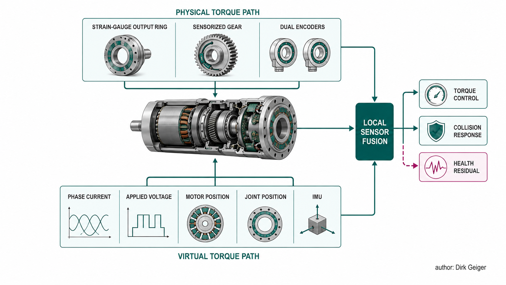
Strain-gauge sensors remain the reference approach. A machined flexure converts torque into strain; a bridge and precision analogue front end measure it. Integration into an output flange, bearing carrier, flexspline or cycloidal component can eliminate a separate sensor body. The 2025 integrated-joint patent places the torque sensor between bearing structure and flexible gear and integrates signal processing on the controller board [14]. This is an instructive architecture, not performance validation.
Sensorized gears exploit deformation already present in the torque path. Their challenge is separating useful load strain from gear meshing, wave-generator deformation, bearing load, temperature and assembly preload. Calibration may be nonlinear and direction dependent. A flexspline can provide high sensitivity but is also a fatigue-critical component. Deposited thin-film gauges could automate sensor production, provided coating adhesion and long-term drift are controlled.
Dual-encoder estimation offers another route. Motor-side and output-side angle measurements reveal torsional deflection across a known elastic element or transmission stiffness. Torque follows from a calibrated stiffness model. Backlash, hysteresis, temperature and time-varying gear contact limit accuracy. The approach is especially useful in an SEA and as redundancy for a physical sensor.
Magnetoelastic sensing measures load-induced changes in magnetic properties of a shaft or ring. It can be contactless and structurally compact, but requires controlled material state, magnetic bias and compensation for temperature and external fields. Optical strain methods offer electromagnetic immunity but add optical alignment and packaging complexity. Bearing-integrated sensing can capture combined load near the mechanical interface, potentially reducing separate structures.
Sensorless observers fuse phase currents, applied voltage, motor position, joint position, IMU data and a dynamic model. They cannot fully eliminate uncertainty in friction and external contact, but they provide low-cost redundancy and continuous plausibility checking. A modest physical sensor combined with an independent observer is strategically stronger than either alone. Persistent disagreement can indicate sensor drift, lubrication change, gear damage or an unexpected contact state.
The semiconductor chain becomes decisive. Bridge sensors need stable excitation, low-offset instrumentation amplification, high-resolution conversion and temperature measurement. Sampling must be synchronized with inverter PWM to reject switching interference. Safety-relevant torque uses independent diagnostic paths, range and rate checks, and defined fault response. Calibration coefficients require protected storage. Local computation can run friction models, sensor fusion and residual-based health monitoring without loading the whole-body network.
10. Semiconductor consequences
A conventional three-phase joint inverter requires six power switches, gate driving, current measurement, DC-link monitoring, rotor-position sensing and a real-time controller. Integration and new motor principles expand that boundary. The semiconductor opportunity should be assessed by joint class rather than by multiplying one bill of materials across every degree of freedom.
10.1 Silicon and GaN serve different loss structures
For a 48–60 V robot bus, low-voltage silicon MOSFETs offer low conduction resistance, mature avalanche behavior, broad sourcing and favorable cost. They are strong candidates for high-current, relatively low-switching-frequency hip and knee inverters. GaN can reduce switching loss and enable higher frequency, smaller passives and compact integration. It is most compelling where switching loss and volume matter: small high-speed motors, printed stators, tightly packaged wrists, or higher-voltage architectures.
The choice cannot be made from device efficiency alone. A slow high-current joint may be dominated by winding copper, MOSFET conduction and gear loss. Raising switching frequency provides little system benefit. A fast low-inductance motor may require high PWM frequency for current quality and benefit materially from GaN. Cable length, common-mode current, current-sensor bandwidth, electromagnetic compatibility and cooling determine the result.
10.2 Current sensing becomes a control and diagnostic asset
Accurate phase current determines torque quality. Low-side shunts are cost effective but face common-mode and sampling-window constraints. Inline phase sensing improves observability at added cost. Magnetic sensors provide isolation and lower insertion loss but introduce offset and bandwidth considerations. Integrated smart joints can place sensing close to switches and calibrate the full chain at end of line.
Current and voltage data also enable winding-resistance estimation, rotor-position observers, contact estimation and health monitoring. The value of a current sensor therefore includes diagnostic accuracy, timing determinism and traceability, not only closed-loop torque error.
10.3 Control migrates toward the joint edge
The local MCU must execute PWM, FOC, encoder processing, torque control, thermal protection and communications with bounded latency. Advanced joints add excitation control, sensor fusion, condition monitoring and safe degraded modes. Hardware accelerators can support trigonometric operations, filtering and resolver or inductive-sensor interfaces. Independent watchdogs and comparators must interrupt unsafe switching even if software fails.
A deterministic Ethernet/TSN or compatible real-time network allows synchronized setpoints, state and energy coordination. The fastest current loop remains local; whole-body torque coordination operates above it. Secure communications and firmware authentication are mandatory because distributed actuators convert network commands directly into physical force.
10.4 Thermal and lifetime intelligence
Winding temperature is rarely measured at its hottest point. Models infer it from housing sensors, current and speed. Integrated temperature sensors, calibrated thermal networks and online resistance estimation can improve protection without excessive derating. Power-stage junction temperature, capacitor life, bearing condition and gear friction should enter the same health model.
Predictive maintenance requires consistent data across a fleet: cumulative torque, thermal cycles, overload events, impact signatures, brake operations and sensor residuals. Local preprocessing reduces network load and protects proprietary raw data. The smart joint can publish health indicators while retaining high-frequency evidence for service diagnostics.
10.5 Architecture fit
| Innovation | Additional electronics | Dominant semiconductor requirement |
|---|---|---|
| QDD PMSM | High-current inverter and precise sensing | Low conduction loss, thermal robustness |
| PCB/printed stator | Very compact high-frequency inverter | Low parasitics, GaN option, EMC control |
| EESM | Rotor excitation channel and rectification | Coordinated field control and safe de-excitation |
| SynRM/SRM | Higher current or phase count | Advanced commutation, ripple suppression |
| Multiphase motor | Additional half bridges and sensing | Independent safety domains and degraded control |
| Integrated torque sensor | Precision analogue front end and ADC | Low noise, synchronization and diagnostics |
| Smart joint | Local MCU, network, security and DC/DC | System integration and qualified safety architecture |
11. Regional and patent signals
The regional pattern is not a simple race toward the same actuator. Each ecosystem is approaching scale from a different industrial starting point.
China’s visible direction is rapid localization and functional integration. The 2025 multifunctional-joint patent combines motor, strain-wave mechanism, torque sensing, brake, magnetic position sensing and control electronics [14]. It is one filing, not a market census, yet it reflects a broader supplier proposition: replace imported precision subsystems with merchant joint modules that can be bought in multiple torque classes. The competitive strengths are speed, dense supplier networks and cost-down iteration. Principal risks are consistency, lifetime evidence, safety qualification and dependence on price-led differentiation.
South Korea contributes materials and automotive industrialization. The KIST CNT work attacks conductor mass and raw-material dependence at the material level [12]. Hyundai’s ecosystem brings bearings, transmissions, high-volume quality systems and electric-actuation experience toward robotics. The strategic question is how quickly automotive component processes can be adapted from smooth vehicle duty to repeated shock, multidirectional load and compact humanoid packaging.
Europe has concentrated competence in rare-earth-reduced machines, precision mechanics, sensing, safety and lifecycle support. Renault’s EESM production record, ZF’s contactless excitation and the Valeo–MAHLE program show sustained work on magnet independence [9]–[11]. Schaeffler’s humanoid positioning explicitly combines components, production integration and lifetime service [15]. Europe’s potential advantage is not the lowest prototype price; it is verified industrial performance, maintainability and supply resilience.
The United States is characterized by robot-OEM vertical integration and software-defined system development. Figure brings actuator and motor production in-house [2]. Boston Dynamics develops an electric Atlas platform while preserving significant architectural opacity [5]. Tesla’s recruitment evidence indicates simultaneous rotary and linear actuator development [7]. Vertical integration accelerates cross-domain optimization but creates large capital, tooling and validation demands.
Japan retains important positions in precision reducers, bearings, encoders, compact motors and production equipment. Public humanoid motor disclosures are limited, so claims about specific next-generation adoption should remain cautious. The likely influence is enabling technology and manufacturing discipline rather than highly publicized motor architecture.
Patents should be read as maps of contested integration space. The older local torque-control patent [8] anticipated electronics collocated at the joint. The newer Chinese filing [14] claims structural integration of motor, gear, brake, sensing and controller. Carbon-conductor patents and research target winding mass. Contactless EESM developments target rotor excitation and rare-earth independence. These clusters identify future bargaining points: who owns the smart-joint boundary, its calibration data, its health model and its replaceable interface.
The missing evidence is as important as the announcements. Few suppliers publish bidirectional efficiency maps, thermal saturation under humanoid duty, backdrive torque, sensor drift, reducer life or production yield. Regional comparisons based only on peak torque, robot price or factory capacity can therefore mislead. Industrial leadership will be determined by verified cost per productive hour, not by the largest announced torque or production target.
12. Technology opportunity matrix
Technology priority must distinguish near-term industrialization from long-term optionality. A concept can be strategically important without being ready for a robot program.
| Technology | Customer value | Maturity for body joints | Likely horizon | Priority |
|---|---|---|---|---|
| Integrated smart joint | Lower assembly, wiring and commissioning | High | 1–3 years | Immediate platform |
| Integrated torque sensing and observers | Safer contact and lower calibration cost | Medium-high | 1–4 years | Immediate differentiation |
| Thermal/lifetime digital model | Higher utilization and predictive service | Medium-high | 1–4 years | Immediate differentiation |
| Amorphous or advanced magnetic core | Lower high-frequency loss and heat | Medium | 2–5 years | Targeted development |
| PCB stator for distal axes | Thin form and automated production | Medium | 2–6 years | Targeted development |
| Multiphase load-bearing joint | Controlled degraded operation | Medium | 3–6 years | Safety research |
| Ferrite-assisted SynRM | Reduced rare-earth exposure | Medium-low | 3–7 years | Architecture study |
| Humanoid-scale EESM | Magnet independence and variable flux | Low despite automotive maturity | 4–8 years | Selective feasibility |
| CNT–metal hybrid winding | Reduced distal mass | Low | 5–10 years | Materials partnership |
| Pure CNT body-joint winding | Potential step in specific mass | Very low | 8–15 years | Monitor and test |
| Multi-axis electromagnetic joint | Lower joint count and natural geometry | Very low | Beyond 8 years | Long-horizon research |
The immediate opportunity is deliberately conservative: improve a known PMSM actuator by integrating sensing, electronics, thermal intelligence, security and manufacturing traceability. This route addresses current customer pain rather than waiting for a material breakthrough. It also creates a stable test platform on which next-generation motors can be compared.
Amorphous cores and printed stators should be segmented. They are not general replacements; they fit high-frequency and flat precision axes respectively. Multiphase designs belong in a safety architecture for load-bearing joints. EESM feasibility should begin with loss and packaging models for waist and hip duty, not with a whole-body commitment. CNT conductors warrant material partnerships and distal-axis demonstrators, with explicit termination and thermal milestones.
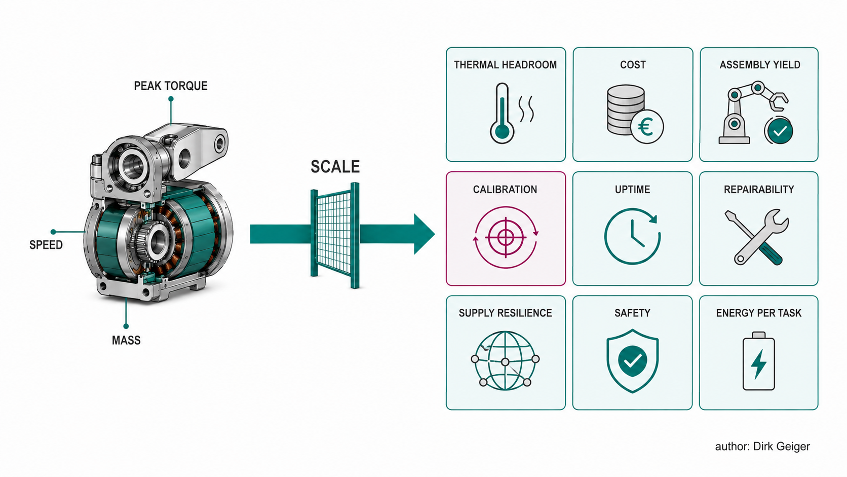
A technology should advance only if it improves one or more mission-level outcomes without unacceptable penalties in the others: energy per useful task, thermal headroom, actuator mass, controllability, availability, lifetime cost, supply resilience and production yield.
13. Validation through mission profiles
A standardized humanoid mission profile is the missing bridge between actuator innovation and robot value. Conventional motor maps remain necessary but insufficient. Humanoid operation contains contacts, rapid torque reversals, static holds, regeneration, idle intervals and thermal recovery. The joint test must reproduce those temporal patterns.
The baseline characterization should measure motoring and generating efficiency over torque and speed, continuous and short-duration torque, winding and inverter temperature, backdrive torque, cogging, output stiffness, backlash, torque-control bandwidth, acoustic emissions and brake behavior. Test conditions must state bus voltage, coolant or airflow, initial temperature and measurement boundary.
A robot mission can then translate whole-body motion into joint trajectories. Each axis receives commanded torque, speed and state at fixed time resolution. The actuator model calculates electrical input, mechanical output, copper loss, core loss, inverter loss, transmission loss and recoverable energy. A thermal network carries loss forward through time. The result exposes repeated peaks and holding periods that a static efficiency map hides.
For emerging technologies, the model must include specific mechanisms. An EESM adds excitation loss. A CNT winding changes resistance, conductor mass and heat transfer. A printed stator changes AC resistance and thermal path. A high-ratio gear adds speed- and load-dependent friction. An SEA stores and releases energy while adding damping. A multiphase drive carries inactive-channel and fault-mode behavior.
Mass should feed back into the mission. A lighter distal motor reduces link inertia and upstream torque. A heavier QDD motor can reduce transmission loss yet increase swing demand. Iteration between actuator and robot model is required until the trajectory and component sizing converge. This prevents a false result in which motor efficiency improves but total robot energy worsens.
Reliability should use the same profile. Rainflow or equivalent cycle counting can classify torque and thermal cycling. Impact events, brake operations, gear reversals and overload duration accumulate damage indicators. The objective is not a single predicted life number; it is a comparable stress signature across actuator concepts.
Five output metrics provide a practical decision set:
- electrical watt-hours per standardized mission;
- useful mechanical work and regenerative recovery;
- maximum winding, inverter and gear temperature;
- productive cycles before thermal derating;
- estimated cost and mass per qualified joint family.
Application metrics can extend this set: watt-hours per pick, per kilogram moved, per metre walked or per productive hour. The mission profile does not replace safety, dexterity or reliability benchmarks. It provides a common dynamic load under which motor, inverter and transmission choices can be compared honestly.
14. Strategic implications
The semiconductor strategy should treat the joint as a configurable platform rather than a collection of isolated sockets. Four reference classes are sufficient to begin: a high-current regenerative leg joint; a thermally constrained waist or shoulder joint; a transparent arm or elbow joint; and a compact precision wrist or neck joint. Each class needs a measured mission, loss model and safety concept.
The leg platform should prioritize low-conduction-loss silicon MOSFETs, high-dynamic-range current sensing, bidirectional energy management, dual position information and a path to multiphase fault tolerance. The waist/shoulder platform should emphasize holding efficiency, brake control, winding temperature and compact cooling. The arm platform should integrate torque sensing and low-latency impedance control. The precision platform can explore GaN, high switching frequency, printed stators and dense integration.
A common electronics and software backbone can span these classes: real-time MCU, three-phase gate driver, calibrated current measurement, local DC/DC conversion, deterministic network interface, secure boot, device identity, functional-safety monitors and health-data storage. Device choice varies with current and voltage; interfaces and diagnostic semantics remain common.
Three development programs follow. First, construct open joint loss and thermal models linked to standardized humanoid missions. Second, build modular reference actuators with replaceable motor, inverter and sensor options, allowing silicon/GaN, gearing and sensing comparisons under the same load. Third, establish ecosystem projects with motor, reducer, sensor and materials partners rather than attempting to own every mechanical technology.
Next-generation research should be gated by explicit evidence. CNT work advances when conductor length, conductivity, termination resistance, thermal cycling and cost meet defined targets. EESM advances when excitation loss and package volume beat a reduced-magnet PMSM over a humanoid mission. Integrated torque sensing advances when drift, crosstalk and calibration time improve without reducing gear life. GaN advances when the complete joint—not the switch alone—shows a material energy, size or thermal benefit.
The commercial proposition is equally systemic. A customer does not ultimately buy switching efficiency. The customer buys more productive cycles, lower derating, safer contact, easier qualification, fewer cables, faster assembly and predictable service. Semiconductor value increases when it measurably improves those outcomes.
15. Conclusion
Humanoid body joints are converging on PMSM-based electric actuation, particularly compact internal-rotor and frameless designs combined with transmissions selected for joint duty. That convergence should not be mistaken for architectural closure. QDD, high-ratio rotary, screw-driven linear and compliant actuators allocate mass, loss, controllability and cost differently.
The strongest next-generation development is the industrialized smart joint: motor, transmission, sensing, inverter, control, communications, safety and health monitoring designed as one serviceable system. It directly addresses assembly, calibration, wiring, thermal utilization and fleet availability. Integrated torque sensing and sensor fusion are central because physical interaction makes force information part of the control architecture, not an optional accessory.
Material and motor innovations remain strategically relevant. Carbon conductors offer exceptional specific-mass potential but remain far from high-current body-joint readiness. Printed stators suit selected flat and precision axes. Amorphous cores can reduce high-frequency loss if manufacturing cost is controlled. EESM, SynRM and SRM approaches reduce rare-earth dependence but transfer burden toward copper, inverter current, excitation hardware and control. Multiphase machines can provide controlled degradation in safety-critical joints.
Every innovation changes semiconductor requirements. Some increase switch count; others increase current, switching frequency, analogue precision or edge computation. Integration raises the importance of security, functional safety and lifetime intelligence. The semiconductor opportunity expands from six power switches toward the electronic architecture of a distributed physical system.
The final selection cannot be made from peak torque, motor efficiency or material novelty. It requires a dynamic, mission-profile-based comparison of energy, temperature, mass, controllability, lifetime and cost. Every watt must be followed from the battery through the inverter, motor and transmission to useful work—and every gram must be traced through the upstream joints that carry it. Under that discipline, the next motor is no longer an isolated component. The joint is the system.
Glossary
- Backdrivability
- The ease with which an external load can move a powered or unpowered actuator through its transmission.
- Cogging torque
- Position-dependent torque caused by interaction between permanent magnets and stator slots when no current is applied.
- Continuous torque
- Torque deliverable without exceeding the actuator's steady-state thermal limits under defined cooling conditions.
- Field weakening
- Control that reduces effective air-gap flux to extend motor speed beyond the base-speed region.
- Frameless motor
- A rotor-and-stator motor kit integrated into the customer's bearings, housing and mechanical structure.
- Holding loss
- Electrical and mechanical loss incurred while maintaining joint torque at little or no output speed.
- Reflected inertia
- Motor and transmission inertia expressed at the joint output after application of the gear ratio.
- Torque transparency
- The degree to which commanded and externally applied torque pass through an actuator without distortion from friction, backlash or inertia.
- Strain-wave gear
- Compact high-ratio reducer using an elastic flexspline deformed by an elliptical wave generator.
- Smart joint
- Integrated actuator combining motor, transmission, sensing, power electronics, control, communications and diagnostics.
Abbreviations
- BLDC
- Brushless direct-current motor
- CNT
- Carbon nanotube
- EESM
- Electrically excited synchronous motor
- FOC
- Field-oriented control
- F/T
- Force and torque
- MCU
- Microcontroller unit
- PMSM
- Permanent-magnet synchronous motor
- QDD
- Quasi-direct drive
- SEA
- Series-elastic actuator
- SRM
- Switched-reluctance motor
- SynRM
- Synchronous-reluctance motor
- TSN
- Time-Sensitive Networking
Sources
- Unitree G1 Humanoid Robot Specifications · n.d.
Product specifications identify internal-rotor PMSM joint motors, dual encoders, local cooling and knee-torque ratings.
https://www.unitree.com/g1/ - BotQ: A High-Volume Manufacturing Facility for Humanoid Robots · 2025-03-15
Figure describes vertical motor and actuator production, manufacturing systems and an initial 12,000-unit annual line capacity.
https://www.figure.ai/news/botq - Introducing Figure 03 · 2025-10-09
Figure reports faster actuators, improved torque density and redesign for commercial use and scalable manufacturing.
https://www.figure.ai/news/introducing-figure-03 - Apollo 2 · 2026
Apptronik describes proprietary actuation designed for efficiency, maintainability, manufacturing scale and supply-chain resilience.
https://apptronik.com/apollo/apollo-2 - An Electric New Era for Atlas · 2024-04-13
Boston Dynamics confirms retirement of hydraulic Atlas and introduction of a fully electric platform for industrial applications.
https://bostondynamics.com/blog/electric-new-era-for-atlas/ - ALLEX, A New Paradigm in Humanoid Robotics · 2025
Maxon describes an ultra-slim frameless motor combined with a low-friction reducer for backdrivable humanoid-arm actuation.
https://www.maxongroup.com/en/knowledge-and-support/blog/allex-a-new-paradigm-in-humanoid-robotics-288628 - Robotics Mechanical Design Engineer, Gears, Optimus · n.d.
Tesla role description confirms gear development for rotary and linear actuator systems coordinated with electromagnetic motor teams.
https://www.tesla.com/careers/search/job/robotics-mechanical-design-engineer-gears-optimus-264636 - Integrated High-Speed Torque Control System for a Robotic Joint · 2011-03-24
Patent describes collocated joint processing, inverter electronics, sensor conditioning and high-speed communication for local torque control.
https://patents.google.com/patent/US20110071680A1 - ZF Makes Magnet-Free Electric Motor Uniquely Compact and Competitive · 2023-09-01
ZF presents contactless inductive rotor excitation intended to remove magnets, brushes and slip rings from synchronous machines.
https://press.zf.com/press/en/releases/release_60480.html - An Electric Motor with No Rare Earths · 2025-10-16
Renault summarizes its production history and roadmap for rare-earth-free electrically excited synchronous vehicle motors.
https://www.renaultgroup.com/en/magazine/energy-and-powertrains/all-about-electric-motors-with-no-rare-earths/ - Valeo and MAHLE Expand Their Product Range of Magnet-Free Electric Motors · 2024-10-14
Companies announce brushless contactless excitation development combining magnet-free rotors, inverters, control and cooling work.
https://newsroom.mahle.com/press/en/press-releases/valeo-and-mahle-expand-their-product-range-of-magnet-free-electric-motors-to-upper-segment-applications-106048 - Core-Sheath Composite Electric Cables with Highly Conductive Self-Assembled Carbon Nanotube Wires · 2025-04-12
Peer-reviewed research demonstrates continuous CNT conductors and a small operational motor while documenting remaining material-scale limitations.
https://link.springer.com/article/10.1007/s42114-025-01302-4 - Amorphous Alloy for Motor Core · n.d.
Proterial reports prototype iron-loss, efficiency and thermal results for an amorphous-stator permanent-magnet motor comparison.
https://www.proterial.com/e/products/soft_magnetism/mtam.html - A Multifunctional Integrated Robot Joint Module · 2025-05-06
Patent integrates motor, strain-wave transmission, torque sensor, brake, position sensing and control electronics within one module.
https://patents.google.com/patent/CN119927962A/en - Humanoid Robots · 2026-04-20
Schaeffler describes smart actuators, production scaling, factory deployment and lifecycle support for industrial humanoid systems.
https://www.schaeffler.com/en/technology-innovation/technology/humanoid-robots/