Chapter 12
The Robot Must Be Electromagnetically Quiet
Designing EMC-Robust Humanoids Where High-Power Motion, Precision Sensing and Real-Time Communication Share One Body
Humanoid robots compress dozens of fast-switching motor drives, precision sensors, high-speed links, radios, safety electronics, and AI compute into a conductive moving body. That density turns electromagnetic compatibility from a late compliance test into a first-order architecture problem. This chapter explains how conducted and radiated interference can corrupt encoders, current sensors, communication links, timing, perception, and even safety decisions while also causing excessive emissions. It connects switching edge rates, cable loops, grounding, shielding, filtering, isolation, differential signaling, PCB layout, and power-domain partitioning into one system-level EMC strategy. Current industrial standards and semiconductor design guidance show that immunity and emissions must be engineered across every port and subsystem. For humanoids, the semiconductor opportunity lies in components and reference architectures that combine efficient switching with controlled slew rate, robust sensing, resilient transceivers, diagnostics, protection, and predictable behavior. A robot that cannot control its electromagnetic environment cannot reliably control the physical world safely.
Electromagnetic Compatibility Becomes a Robot Architecture Problem
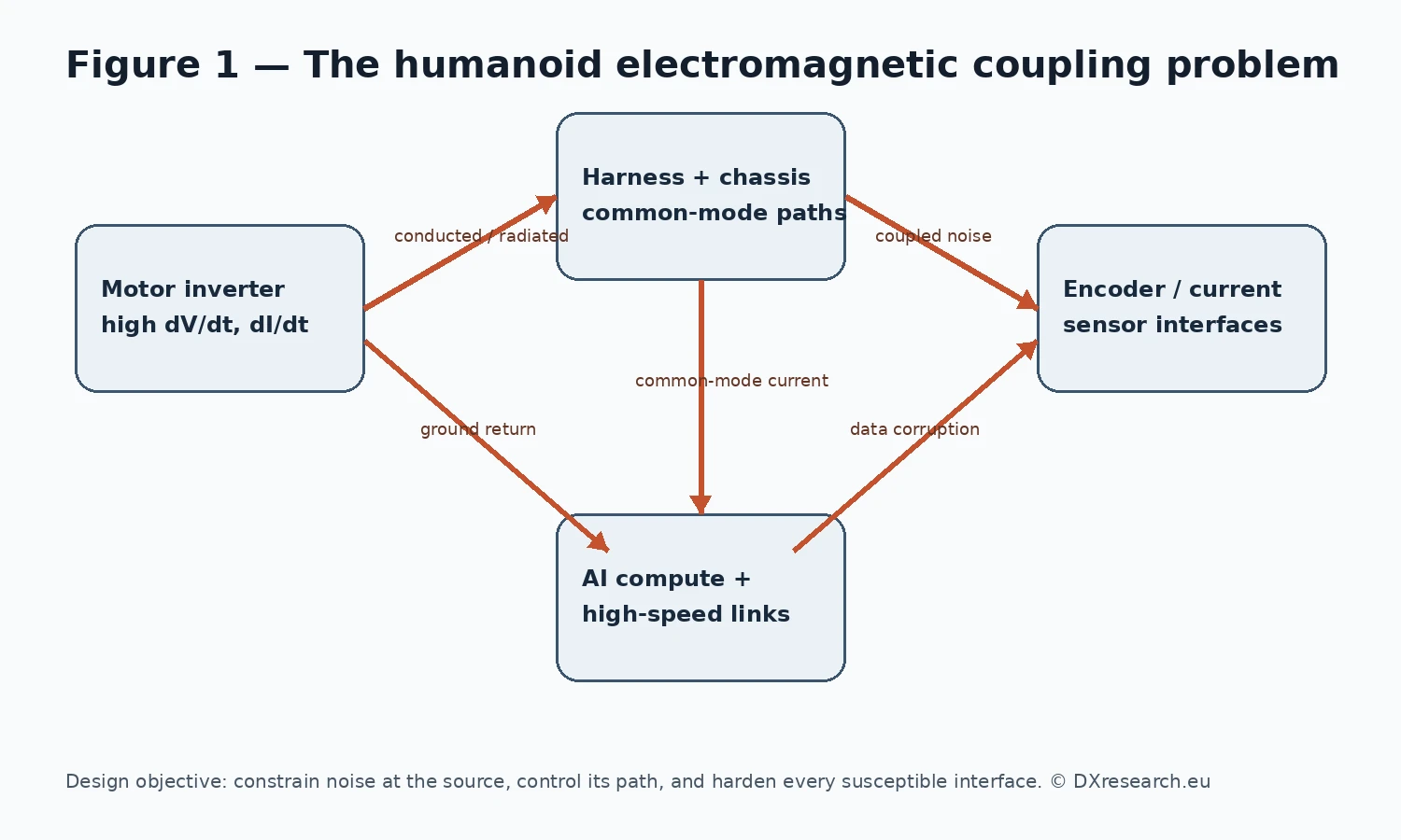
A humanoid robot is an unusually dense electromagnetic system. Dozens of motor phases are switched at high current within centimeters of magnetic position sensors, current-sense amplifiers, inertial sensors, cameras, microphones, high-speed serial links, wireless radios and safety controllers. Flexible harnesses move continuously, chassis impedances change with posture, and return-current geometry is constrained by joints rather than by an ideal cabinet. One subsystem can therefore become both an electromagnetic noise source and a noise victim.
Industrial electromagnetic compatibility has often been treated as a qualification discipline after electrical and mechanical design converge. That approach is risky for humanoids. IEC 61000-6-2 defines generic immunity requirements for industrial equipment, while IEC 61000-6-4 defines generic emissions requirements where no dedicated product-family standard applies [ref-iec-61000-6-2-2016] [ref-iec-61000-6-4-2018]. These standards establish the central engineering reality: equipment must tolerate its electromagnetic environment and limit the disturbances it creates.
For a robot, failure is not limited to radio interference. Electromagnetic interference can alter an encoder edge, disturb a current measurement, inject a communication error, trigger a reset, corrupt a sensor sample or create timing uncertainty. Small electrical errors can propagate into torque errors, balance corrections, false obstacle perception or diagnostic faults. ISO 10218-1:2025 reinforces the broader safety expectation that industrial robots use inherent risk reduction and protective measures [ref-iso-10218-1-2025]. EMC therefore sits upstream of dependable control and, in some architectures, upstream of safety evidence.
Why Humanoids Are Harder Than Conventional Machines
Many switching converters share a compact moving structure
Humanoid actuation concentrates many inverters, DC/DC converters and switching regulators into the torso and limbs. Every bridge transition produces high dV/dt and dI/dt. Parasitic capacitance converts voltage edges into common-mode current; stray inductance converts current edges into voltage overshoot and ringing. The same mechanical structures that save mass can become return paths or antennas.
Recent Infineon gate-driver guidance recommends controlling switching speed, minimizing gate and switching loops, keeping sensitive current-sense traces away from high-dV/dt nodes, and using tightly placed decoupling [ref-ifx-2edl90xg3-2026]. A compact 80 V, 3.5 kW BLDC reference design also illustrates deliberate separation of power and analog-ground regions and careful multilayer routing [ref-ifx-80v-35kw-bldc-2025]. Humanoid scaling turns these board-level choices into repeated system-level rules.
Precision sensing lives beside the disturbance source
Modern humanoids need joint angle, rotor position, current, load, inertial motion and contact information with high bandwidth and low latency. Infineon’s TLE480x EMC guidance describes how high-frequency sensing and digital output interfaces require decoupling, filtering and layout discipline [ref-ifx-emc-tle480x-2025]. Texas Instruments and Analog Devices make the same point for motor encoders: exposed interfaces require strong immunity to common-mode voltage, electromagnetic fields and transient events [ref-ti-encoder-emc-2015] [ref-adi-endat-rs485-an1397].
The chassis is articulated, not static
Traditional industrial drives benefit from fixed cabinets, stable grounding points and predictable cable routing. Humanoids have movable limbs, rotating joints, detachable modules, composite covers and weight-driven structural compromises. Shield continuity, bonding impedance and cable geometry can change with mechanical configuration. An EMC solution that works on a bench harness can degrade after integration into the final kinematic structure.
Four Layers of EMC-by-Architecture
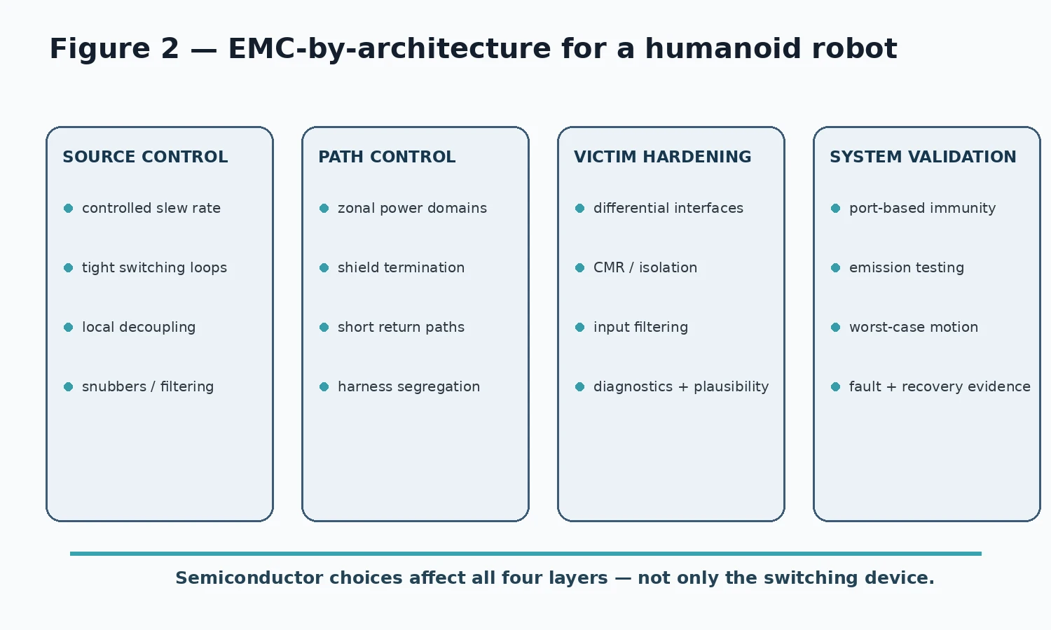
1. Control the disturbance at its source
The cheapest electromagnetic disturbance is the one never generated. Motor-control design should treat slew-rate control as a system variable rather than a fixed gate-driver setting. Faster switching can reduce losses or passive-component size, but can also increase ringing, common-mode current and radiated energy. Gate resistance, driver strength, dead time, snubbers, local decoupling and power-loop geometry should be optimized together.
This creates a semiconductor-level trade space. Power MOSFETs or GaN switches, gate drivers, current sensing and controller timing jointly shape the waveform. Devices with configurable drive strength, strong common-mode robustness, integrated diagnostics or current measurement can reduce uncertain external interactions. The goal is not simply the fastest edge; it is the fastest edge that preserves thermal efficiency, control quality and EMC margin.
2. Control the propagation path
Noise that is generated must be given a controlled path. That means minimizing high-frequency loop area, providing low-impedance returns, segregating noisy and sensitive harnesses, managing shield termination, partitioning power domains and avoiding inadvertent chassis currents. In a humanoid, this naturally supports zonal electronics: local motor-control and sensing nodes can keep high-current commutation loops short while transmitting processed information over robust differential links.
3. Harden every susceptible interface
Victim hardening combines electrical margin with information-level plausibility. Differential signaling, common-mode rejection, isolation, filtering, hysteresis, ESD protection and transient suppression reduce the probability that noise becomes a valid-looking signal. Remaining errors should be detected by protocol checks, redundant sensing, range checks, timing supervision or state-estimator confidence.
A disturbance that produces a clearly invalid frame is easier to manage than one that subtly biases a sensor while remaining syntactically valid. Semiconductor diagnostics therefore have architectural value: signal-quality flags, supply monitoring, overvoltage detection, watchdogs, CRC-protected interfaces and fault memories create evidence software can use to distinguish physical motion from electrical corruption.
4. Validate the robot in realistic electromagnetic states
Component qualification is necessary but insufficient. Humanoid EMC validation should exercise standing, walking, high-torque acceleration, regenerative braking, simultaneous multi-axis motion, charging, wireless communication and worst-case compute loading. Those states create different switching spectra and current-return patterns. Port-based immunity and emission tests should be combined with robot-specific functional monitoring.
Pass/fail should include more than whether a controller resets. Engineers should record encoder residuals, current-sense deviations, communication error counters, estimator confidence, watchdog events and safety-channel diagnostics while disturbances are applied. This turns EMC testing from a certification gate into system characterization.
Electromagnetic Robustness Is a Semiconductor Value Driver
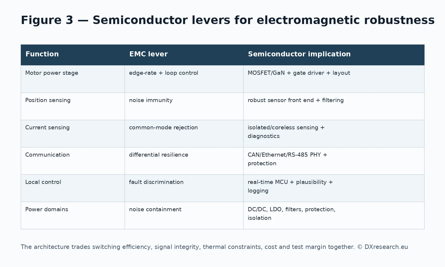
Infineon’s humanoid application architecture frames robotics as a system of motor control, sensing, power, compute, safety, security and connectivity [ref-ifx-humanoid-2026]. EMC cuts horizontally across all these functions. That makes it a strong example of why semiconductor value in Physical AI extends beyond individual component specifications.
| Robot function | EMC risk | Semiconductor design lever |
|---|---|---|
| Joint inverter | High dV/dt, dI/dt, ringing | Power switches, configurable gate drivers, current sensing, local control |
| Position sensing | Coupled noise, ground movement | Robust sensor front end, filtering, diagnostic interfaces |
| Current / torque estimation | Common-mode transients | High-CMR sensing, isolation, synchronized ADC capture |
| Robot network | Common-mode noise, ESD, transient faults | Differential PHYs, protection, CRC and link diagnostics |
| AI compute power | Fast load transients, broadband emissions | Point-of-load conversion, power integrity, decoupling, sequencing |
| Safety controller | False inputs or resets | Robust MCU, watchdogs, monitored supplies, independent diagnostics |
The key value driver is predictable behavior at interfaces. A motor-control device that reduces switching losses but creates uncontrolled common-mode stress can move cost into shielding, filtering or validation. A sensor with excellent static accuracy but weak disturbance immunity can degrade system accuracy under motion. A transceiver with robust common-mode behavior can simplify harness design and improve diagnostic coverage. These cross-domain effects are why semiconductor reference architectures matter.
From EMC Compliance to Electromagnetic Observability
The next step is to make electromagnetic health partially observable during operation. Robots already record motor currents, bus voltages, temperatures, communication error counters and diagnostic flags. Those signals can be correlated with operating state to identify emerging EMC problems: a connector shield that degrades, a cable that moves into a high-field path, a motor phase with abnormal ringing, or a power-domain fault that increases common-mode current.
This does not require turning every humanoid into a spectrum analyzer. It requires exposing enough semiconductor diagnostics to detect when electrical margins are eroding. In fleet operation, repeated correlation between poses, loads and error signatures could become a maintenance signal. EMC then links naturally to uptime without duplicating the uptime thesis: the focus here is the electromagnetic mechanism and architecture that contains it.
Engineering Implications for Humanoid Platform Design
EMC requirements should be allocated by zone and interface before PCB design. Each actuator module should define allowed conducted noise, switching-edge targets, cable and shield assumptions and interface immunity. The robot should minimize long analog paths, convert signals locally where possible, and transport data over robust differential links. Grounding and shielding must be co-designed with mechanical structure because articulation and service connectors are electrical design parameters. Validation should use robot mission states rather than static idle conditions. Semiconductor selection should explicitly include common-mode robustness, diagnostic visibility, transient behavior and configurable switching characteristics.
This also improves modularity. A robot OEM can define EMC interface contracts for actuator, sensor and compute modules. Suppliers can qualify modules against a shared electrical environment rather than relying only on component-level data sheets. Such contracts can shorten integration cycles and make modular robot architectures more credible.
Conclusion
Humanoid robots will not become dependable physical workers merely by adding more compute or stronger actuators. Their electronics must coexist inside an extremely dense, moving electromagnetic environment. EMC is therefore a foundational architecture discipline connecting power switching, sensing, communication, control and safety.
The design principle is direct: control the source, control the path, harden the victim and validate the complete system under realistic motion. Semiconductors influence every layer through switching behavior, sensing topology, interface robustness, protection and diagnostics. As humanoids scale from prototypes to manufactured fleets, electromagnetic robustness will become a measurable differentiator in reliability, safety, integration effort and field service. A robot that cannot control its own electromagnetic noise cannot consistently trust what it senses, communicates or commands.
References
- International Electrotechnical Commission. IEC 61000-6-2:2016 — Electromagnetic compatibility (EMC) — Generic standards — Immunity standard for industrial environments. 2016-08-10. https://webstore.iec.ch/en/publication/25630
- International Electrotechnical Commission. IEC 61000-6-4:2018 — Electromagnetic compatibility (EMC) — Generic standards — Emission standard for industrial environments. 2018-02-07. https://webstore.iec.ch/en/publication/26622
- International Organization for Standardization. ISO 10218-1:2025 — Robotics — Safety requirements — Part 1: Industrial robots. 2025-02. https://www.iso.org/standard/73933.html
- Infineon Technologies. Basic design consideration and layout recommendations for EMC robustness — TLE480x family. 2025-05-26. https://www.infineon.com/assets/row/public/documents/24/42/infineon-basic-design-consideration-and-layout-recommendations-for-emc-robustness-applicationnotes-en.pdf
- Infineon Technologies. EiceDRIVER 2EDL90xG3 — 120 V current sensing integrated gate driver for Si and GaN. 2026-05-07. https://www.infineon.com/assets/row/public/documents/non-assigned/49/infineon-2edl90xg3-datasheet-datasheet-en.pdf
- Infineon Technologies. 80 V, 3.5 kW BLDC motor driver inverter — REF_80VDC_3.5KW_OPE2. 2025. https://www.infineon.com/assets/row/public/documents/24/42/infineon-80v-3.5kw-bldc-motor-driver-inverter-applicationnotes-en.pdf
- Texas Instruments. Designing an EMC-compliant interface to motor position encoders — Part 1. 2015-08-31. https://www.ti.com/document-viewer/lit/html/SSZTC91
- Analog Devices. AN-1397: Using the ADM3065E 50 Mbps RS-485 Transceiver in EnDat Motor Control Encoder Applications. 2017. https://www.analog.com/en/resources/app-notes/an-1397.html
- Infineon Technologies. Humanoid robots application presentation. 2026-06-08. https://www.infineon.com/de/gated/infineon-humanoid-robots-applicationpresentation-en_92915ea9-7f47-4893-9d7e-234f52ef8e35
Glossary
- Common-mode current
Unwanted current flowing in the same direction on multiple conductors relative to a shared reference, often driving radiated emissions.
- Electromagnetic compatibility
The ability of equipment to function acceptably in its electromagnetic environment without introducing intolerable electromagnetic disturbances.
- Electromagnetic interference
Electromagnetic disturbance that degrades, interrupts, or corrupts the intended operation of an electrical or electronic function.
- Slew-rate control
Intentional control of voltage or current transition speed to balance switching loss, overshoot, ringing, and electromagnetic emissions.
References
- 80 V, 3.5 kW BLDC motor driver inverter — REF_80VDC_3.5KW_OPE2. Source
- AN-1397: Using the ADM3065E 50 Mbps RS-485 Transceiver in EnDat Motor Control Encoder Applications. Source
- Basic design consideration and layout recommendations for EMC robustness — TLE480x family. Source
- Designing an EMC-compliant interface to motor position encoders — Part 1. Source
- EiceDRIVER 2EDL90xG3 — 120 V current sensing integrated gate driver for Si and GaN. Source
- Humanoid robots application presentation. Source
- IEC 61000-6-2:2016 — Electromagnetic compatibility (EMC) — Generic standards — Immunity standard for industrial environments. Source
- IEC 61000-6-4:2018 — Electromagnetic compatibility (EMC) — Generic standards — Emission standard for industrial environments. Source
- ISO 10218-1:2025 — Robotics — Safety requirements — Part 1: Industrial robots. Source