Magazine Article
The Robot Must Know When Electricity Escapes
Why Insulation Integrity Becomes Runtime Intelligence in High-Power Humanoids
A humanoid can appear electrically healthy while insulation quietly deteriorates. As batteries, inverters, motors, chargers and moving harnesses share a touchable conductive body, insulation becomes a runtime system property. Continuous monitoring, contextual diagnostics and controlled responses can turn an invisible electrical weakness into actionable health information before it becomes a consequential fault.
Insulation is a runtime property
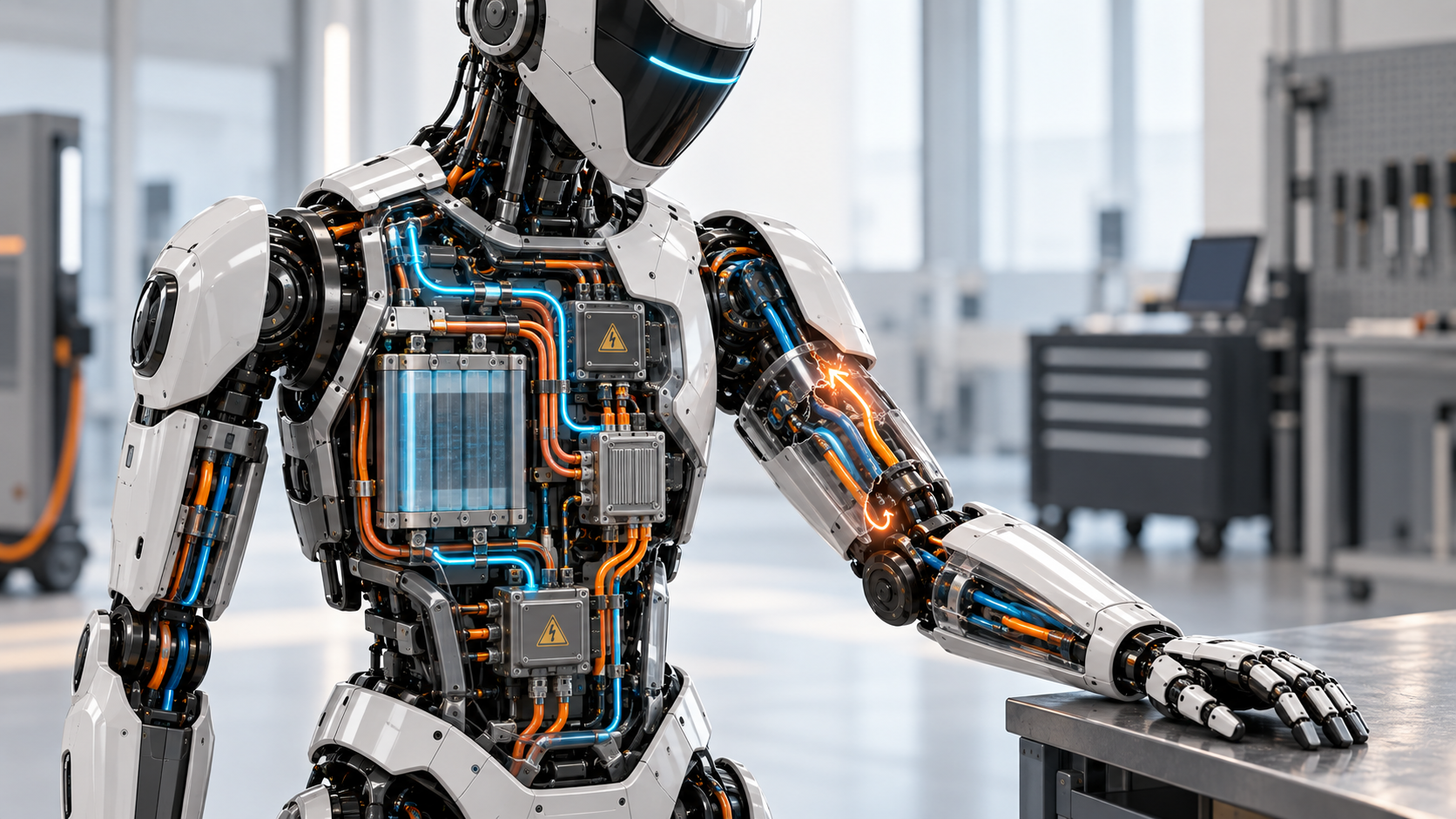
A humanoid can look perfectly healthy while electricity is beginning to find a way out. There may be no smoke, no dramatic spark and no stopped joint. The robot may still walk, lift and charge as expected. Yet somewhere inside its body, moisture has entered a connector, a harness has rubbed against an edge, contamination has bridged two surfaces or repeated motion has weakened a layer of insulation. Electrically, the machine is no longer quite the machine that left the factory.
That is what makes insulation integrity so important in high-power humanoids. A robot gathers a battery, a DC bus, dozens of motor inverters, motors, sensors, communication links, charging hardware and service interfaces inside one compact, articulated structure. Much of that structure is conductive. People may touch it, guide it, maintain it or work beside it. Every reach and step moves electrical conductors through joints where packaging space is scarce and mechanical stress is routine. Insulation is therefore not merely a material specification printed on a cable drawing. It is a condition of the complete operating system.
Traditional electrical thinking can make the problem appear static: choose a voltage class, define creepage and clearance, apply protective bonding, qualify the insulation and test the finished machine. All of those activities matter. But the robot will then leave the test bench. It will kneel near a wet floor, grip a grounded machine, connect to a charger, accept a diagnostic cable, carry conductive tools and accumulate thousands of hours of vibration and articulation. Its electrical boundary conditions will change while the mechanical body appears unchanged.
The better question is not simply whether the robot is grounded. It is whether the relationship between energized conductors, exposed structure, earth, chargers, tools and nearby people remains known and controlled in every mission state. Once that relationship is treated as observable system information, insulation can move from a commissioning measurement to a source of runtime intelligence.
A mobile robot does not have one electrical reference
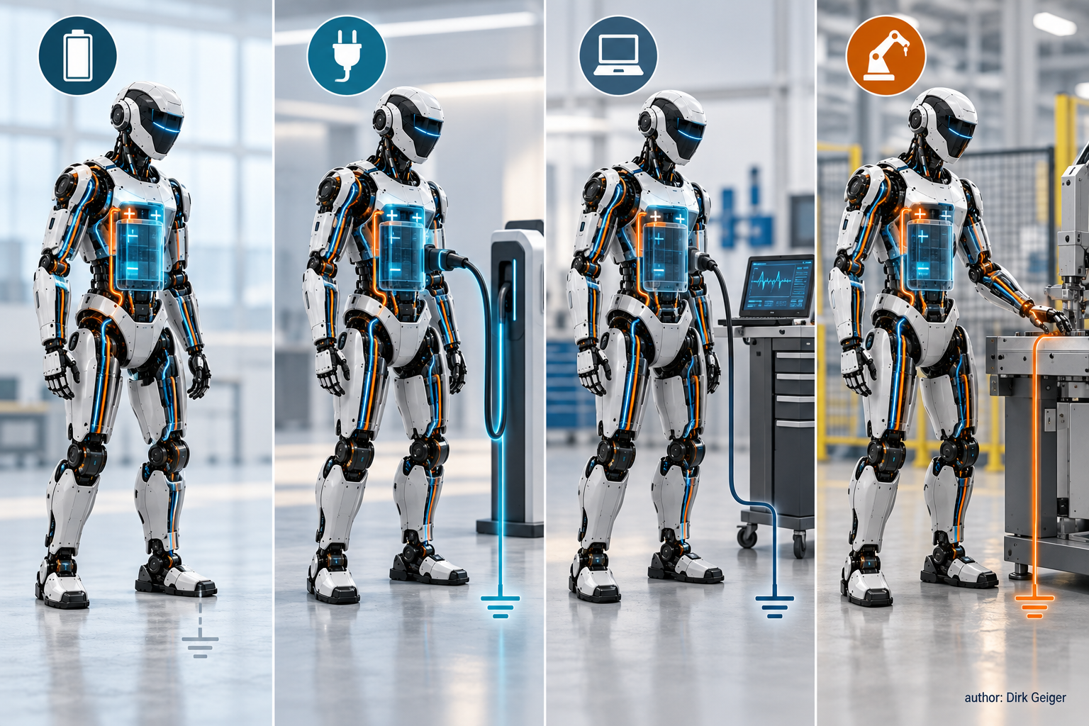
“Ground” is one of the most familiar symbols in electrical engineering and one of the easiest to oversimplify. In a stationary installation, protective earth, bonding and the supply arrangement are usually designed as part of infrastructure that changes little during operation. A mobile robot lives a more complicated life. While moving autonomously, its battery-powered system may have no permanent conductive connection to earth. During charging, it becomes part of another electrical installation. During service, oscilloscopes, programmers or bench supplies may create additional references. During work, a gripper or tool can touch a grounded machine frame. The robot has not changed its silhouette, but its electrical topology may have changed materially.
This does not mean every humanoid should use an unearthed power architecture, nor that one grounding concept fits every machine. It means grounding, protective bonding, galvanic isolation, charging topology and service interfaces cannot be designed as separate checklist items. A low-voltage logic domain, a traction-like DC domain and an externally powered tool may each have different isolation boundaries. A charger can intentionally connect domains that remain separated during autonomous motion. Test equipment can create an unintended return path. Protective bonding may keep exposed conductive parts at a controlled relationship under a fault, but its exact role depends on the architecture and applicable requirements.
Mission-state thinking makes these relationships explicit. What is connected in autonomous mode? What changes when the dock closes its contacts? Which conductive parts are accessible during service? Can a technician connect an earthed instrument across an isolated domain? What happens when both hands touch equipment with a different reference? Can an optional tool introduce its own power supply or cable shield? These are not edge cases. They are ordinary transitions in the working life of a general-purpose robot.
The practical result is an electrical state model alongside the mechanical and functional state model. The robot already knows whether it is walking, charging, carrying a load or awaiting service. It should also know which power domains are energized, which isolation boundaries are expected, which external connections are present and what insulation signature is plausible for that configuration. A measurement that looks suspicious in one state may be normal in another because a charger filter or tool interface has changed the system’s capacitance to structure. Context prevents a monitor from becoming either too trusting or too noisy.
This is where a simple schematic symbol becomes an architectural discipline. The reference condition has to be intentionally created, detected where possible and considered whenever the machine changes mode. Ground is not a fixed place inside the robot. It is a relationship that the system must understand.
The first fault changes the system
An insulation fault rarely begins with the cinematic event that safety illustrations like to show. More often it starts as a small change. A connector seal ages. Conductive dust accumulates. Coolant or cleaning fluid reaches a surface. A cable jacket develops a worn patch. A motor winding’s insulation is stressed by heat and switching voltage. Resistance between an active conductor and the robot’s conductive structure falls gradually, perhaps intermittently and perhaps only in one posture.
In an unearthed system, the first insulation fault changes the electrical relationship without necessarily producing the large fault current associated with a hard short circuit. That can be valuable because operation need not always end at the first detectable deviation. It can also be dangerous if the changed topology remains invisible. A second fault, an external earth connection or a person contacting another potential can complete a more consequential path. Whether limited continued operation is acceptable is never a universal answer; it belongs to the robot’s hazard analysis, electrical architecture, safety functions and applicable standards.
IEC 61557-8 provides an important architectural precedent. It specifies requirements for insulation monitoring devices that permanently monitor insulation resistance to earth in unearthed AC and DC IT systems, including unearthed DC systems up to 1,500 V DC. The standard does not turn a humanoid into a compliant product by itself, and it does not prescribe a universal shutdown value for robots. It demonstrates something more fundamental: insulation condition can be observed continuously rather than discovered only during periodic testing or after a hard failure.
That distinction changes the engineering conversation. A single pass/fail result answers whether the measured system crossed a limit at a particular moment. A monitored trend can reveal direction, recurrence and context. Did insulation resistance decline slowly over weeks? Does it dip only when the right knee is deeply flexed? Did the signature change after a tool was fitted or after cleaning? Does the deviation disappear when one inverter domain is isolated? None of these clues proves a specific physical defect on its own, but together they can convert an invisible electrical weakness into a diagnosable system condition.
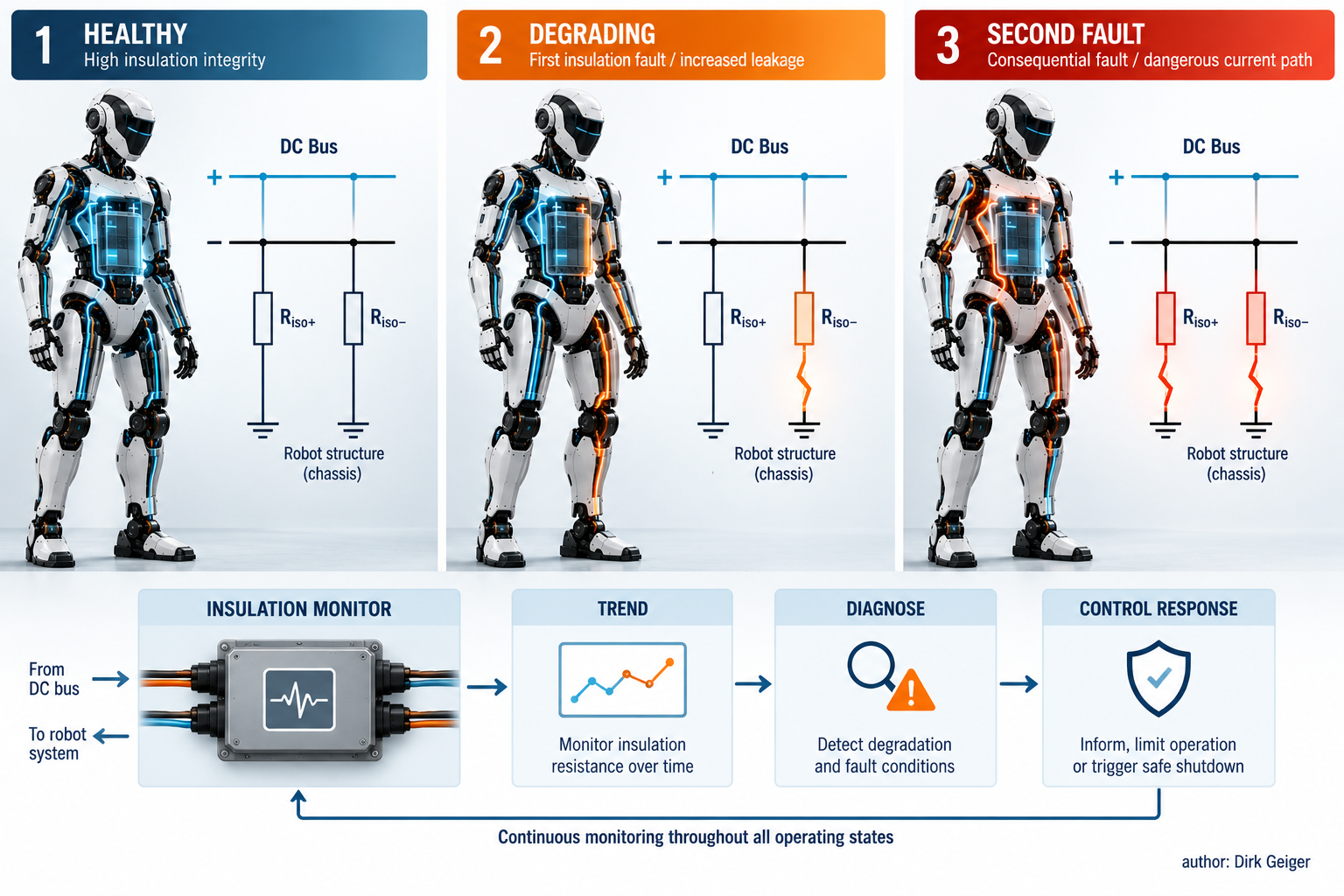
The first fault therefore deserves more than an alarm lamp. It is a topology change. The robot needs a defined response that matches risk and mission state: log and schedule service, warn an operator, inhibit charging, reduce available power, isolate a suspect branch, move to a safe pose or shut down. The response must be designed, not improvised after the first field incident. No threshold should be copied blindly from another product class. Voltage, stored energy, capacitance, accessible parts, environmental exposure, measurement uncertainty and the potential current path all matter.
Inverters make monitoring harder
Measuring insulation on a quiet cable is straightforward compared with observing it inside a working humanoid. Motor inverters switch rapidly. Their voltage edges couple through parasitic capacitances in semiconductor devices, heat sinks, motor windings, cables and filters. EMC components deliberately create controlled high-frequency paths. Long or distributed harnesses add capacitance to the conductive structure. Multiple inverters operate with different duty cycles, while chargers and external tools can introduce additional filters and references.
The monitor therefore sees more than pure resistance. It sees a time-varying electrical environment shaped by switching states, common-mode voltage, distributed capacitance and the measurement method itself. A motor accelerating under load may create a different background than the same joint holding position. A charging robot may look electrically different from a free-standing robot even when both are healthy. Fast transients can interfere with a measurement designed to track a slower insulation change. Aggressive filtering can calm the signal while hiding useful dynamics or delaying detection.
Adjacent experience from electric vehicles shows that continuous insulation monitoring can operate around an isolated high-voltage drive system. Bender, for example, describes its IR155 family as monitoring insulation resistance between active propulsion conductors and chassis reference on both the DC side and AC motor side. This is useful company evidence for feasibility, not proof that a vehicle solution can be dropped unchanged into a humanoid. Robots may operate at different voltages, distribute power through many more articulating branches, attach tools, touch people in different ways and enter service configurations that vehicles do not.
The hardest cases are often intermittent. Imagine a leakage path that appears only when a shoulder harness is twisted, or contamination that becomes conductive only under humidity. A slow measurement may miss a posture-dependent event; a sensitive monitor may report nuisance alarms during switching activity. Solving this requires coordination among the monitor, inverter controls, system MCU and power-distribution architecture. Measurement windows can be associated with known operating states. Domains can be energized or isolated in a diagnostic sequence. Signal processing can separate repetitive switching signatures from persistent change, provided the limits and confidence of that classification remain explicit.
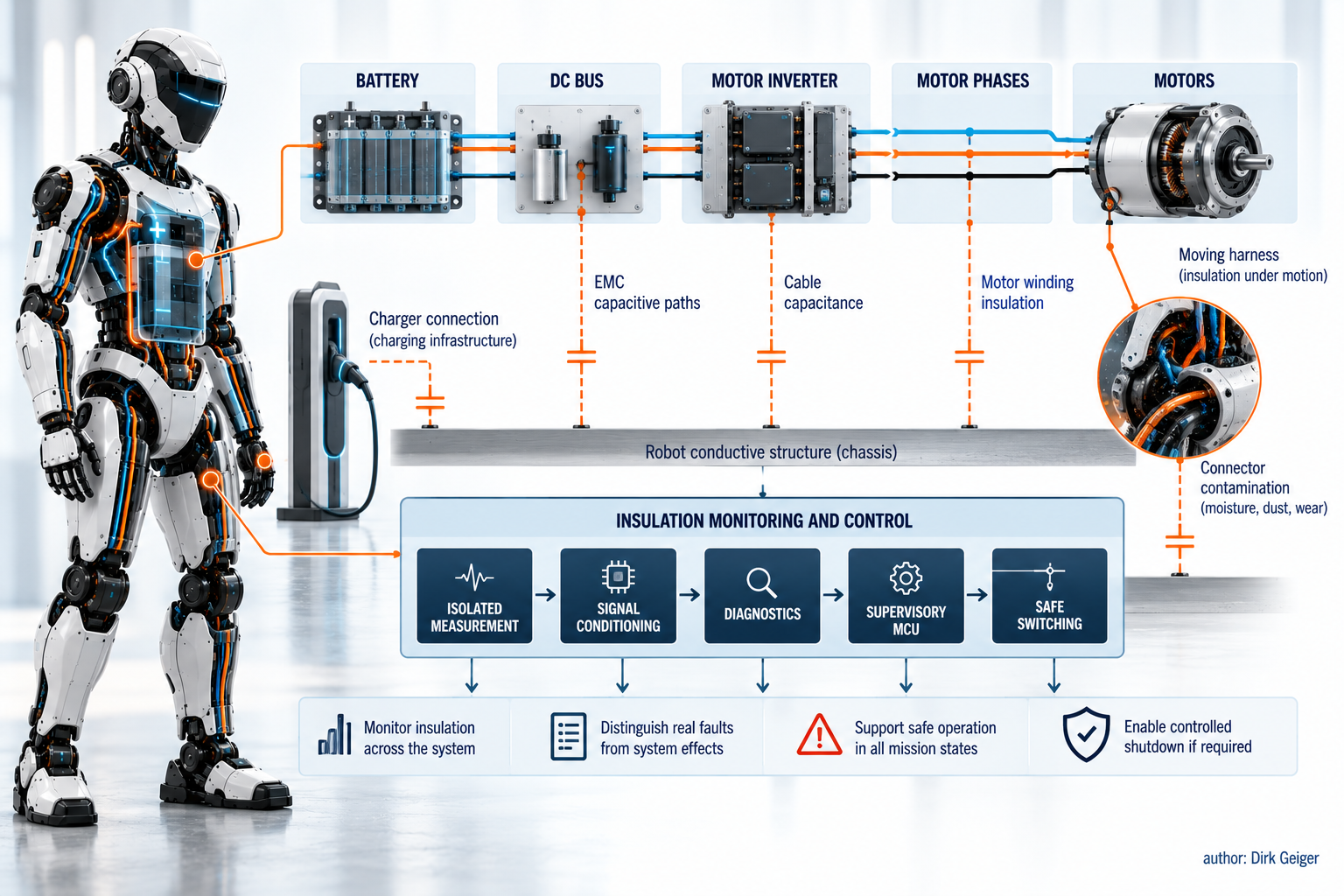
Insulation monitoring is consequently a system measurement problem, not a resistance meter bolted onto the battery. The architecture must define where the monitor observes, which domains can be distinguished, how capacitance affects response time, what happens during charging and how the function behaves when its own sensing path is compromised. Good measurement hardware is essential. Equally important is designing the robot so the resulting information can be interpreted.
Diagnostics can make degradation visible
Robots already generate an enormous amount of operational context. Joint angles, motor currents, temperatures, vibration indicators, communication errors, power states and maintenance histories are available somewhere in the control system. Insulation data becomes much more valuable when it is correlated with that context. A falling value during all operating states suggests something different from a brief deviation at one joint angle. A change coinciding with charging points toward a different search area than one appearing during high-torque wrist motion.
The opportunity is condition-based maintenance for electrical integrity. Instead of waiting for a binary fault, the robot can establish a healthy baseline and look for meaningful deviation. Absolute insulation measurements remain important, but trend, rate of change, repeatability and localization can improve diagnostic confidence. Service software could present a technician with evidence such as: degradation began after a connector replacement; the event recurs during left-hip flexion; isolating the distal leg domain restores the expected signature. That is far more actionable than “insulation fault somewhere.”
Care is needed because correlation is not causation. A communication disturbance and an insulation dip occurring together do not prove one caused the other. Temperature and humidity can shift measurements without indicating imminent failure. Measurement uncertainty, component tolerances and state transitions can produce apparent trends. Diagnostics should therefore communicate confidence and preserve raw evidence rather than manufacturing certainty. The machine may know that a domain is suspicious before it knows which connector is contaminated.
Localization can be designed into the power architecture. Contactors or protected solid-state switches can separate branches. Isolated sensing can observe voltages or currents on either side of a boundary. Distributed controllers can report whether anomalies occur locally. A structured diagnostic routine can energize domains in sequence when the robot is in a safe state. These capabilities add cost, area, software and failure modes of their own, so the right granularity depends on the value of uptime, the energy in each domain and the practicality of service.
The reward is not merely preventing electric shock. Degrading insulation can create intermittent resets, corrupted sensor behavior, nuisance trips or unexplained inverter faults long before a dramatic event. Finding the electrical cause early reduces time spent replacing healthy modules. It can also reveal a mechanical design weakness: a harness route that fails repeatedly, a sealing concept that cannot tolerate cleaning or a connector location that traps contamination. Runtime evidence feeds the next design iteration.
The semiconductor consequence
Making insulation observable requires a chain of semiconductor functions. An insulation-monitoring front end must interact safely with the power domain it observes. Precision analog circuitry has to extract a meaningful signal amid common-mode voltage, switching noise and distributed capacitance. Galvanically isolated measurement and communication can carry information across domain boundaries without quietly defeating them. Microcontrollers execute diagnostics, correlate operating context and supervise the response. Gate drivers and protected switches help place power domains into defined states. Power devices ultimately connect, isolate or discharge energy according to the safety concept.
No single component creates electrical integrity. The value lies in how the functions cooperate. An accurate measurement with no credible response path is incomplete. A fast switch without independent knowledge of its state may create false confidence. A powerful diagnostic algorithm cannot compensate for an architecture in which every branch is permanently tied together and impossible to distinguish. Semiconductor selection therefore begins with questions about observability and controllability: What must be measured? What can be isolated? Which failures must remain detectable? What information is needed after power has been removed?
Integration creates attractive possibilities and uncomfortable trade-offs. Combining measurement, diagnostics and communication can reduce size and simplify interfaces. Independence may still be required between the function that controls motion and the function that decides whether electrical energy remains safely contained. Higher switching speed can improve inverter efficiency while increasing common-mode stress and measurement complexity. Distributed power conversion can shorten high-current routes but multiply energized nodes. More sensors can improve visibility while adding isolation barriers, connectors and software.
The design goal is not maximum electronics. It is sufficient, trustworthy evidence for the robot to take the right action. That might mean a central monitor for a compact low-energy platform. A larger machine could benefit from hierarchical monitoring: a system-level view paired with switchable or locally observed domains. The charger interface may need its own logic because connecting to infrastructure changes the reference condition. Service mode may require restrictions that do not apply during autonomous motion.
This is also a data architecture. Measurements need timestamps, state context and diagnostic identifiers. Fault histories must survive a controlled shutdown. Software updates cannot silently change thresholds or interpretation without configuration control. Cybersecurity matters because an attacker who can suppress an insulation warning or command inappropriate switching can interfere with an electrical safety function. Runtime intelligence is credible only when sensing, computation, communication and actuation are engineered as one chain.
Design insulation around mission states
A humanoid is a moving electrical installation that repeatedly changes its relationship with the outside world. It can be isolated while walking, connected while charging, opened during service and electrically coupled to tools or machines during work. Inside, its inverters generate fast common-mode activity while harnesses flex, connectors age and contaminants find small paths through dense packaging. A one-time insulation test cannot describe that entire life.
The durable approach begins with mission states. For each state, define the intended electrical references, energized domains, accessible conductive parts, external connections and credible fault paths. Then define what the robot must observe and how confidently it must observe it. Decide which changes require a warning, controlled derating, isolation, charging inhibition, a safe pose or immediate shutdown. Validate the behavior with the real capacitance, switching patterns, environmental exposure and service equipment of the machine—not only with an idealized schematic.
That work produces business value as well as safety value. Earlier fault recognition can protect uptime, shorten troubleshooting and turn recurring field failures into design evidence. Domain-level diagnostics can guide a technician to a leg, arm or tool interface instead of triggering a costly search through the whole machine. A well-designed response may preserve limited safe functionality where an undifferentiated alarm would stop everything. These benefits depend on rigorous architecture; they cannot be claimed from a sensor alone.
Electrical energy is safe only while the system keeps it within intended boundaries and responds when those boundaries change. For high-power humanoids, knowing the battery’s state of charge is not enough. The robot must also know whether its energy remains contained, how certain that knowledge is and what to do when certainty begins to disappear. Insulation integrity has become runtime intelligence.
Glossary
- Insulation monitoring device
- A device that continuously monitors insulation resistance in an unearthed electrical system.
- Insulation resistance
- Resistance between energized conductors and an electrical reference such as conductive structure or earth.
- Insulation fault
- An unintended reduction of insulation between an energized circuit and another conductive part or electrical reference.
- Protective bonding
- Electrical interconnection of conductive parts intended to support protection against electric shock under fault conditions.
- Parasitic capacitance
- Unintended capacitance between circuit nodes or structures that can carry displacement current when voltages change.
- Leakage current
- Current flowing through an unintended or normally non-current-carrying path, including insulation and capacitive paths.
- Unearthed system
- A power system whose active conductors are not intentionally connected directly to earth, or are connected through impedance.
- Electrical reference
- The potential against which another electrical potential is interpreted, such as chassis, protective earth or circuit common.
Abbreviations
- AC
- Alternating current
- DC
- Direct current
- EMC
- Electromagnetic compatibility
- IMD
- Insulation monitoring device
- PE
- Protective earth
- MCU
- Microcontroller unit
- IT system
- IEC earthing-system designation for a system isolated from earth or connected to earth through impedance
Sources
- IEC 61557-8:2014 — Insulation monitoring devices for IT systems · 2014-12-11
IEC requirements for devices that permanently monitor insulation resistance to earth in unearthed AC and DC IT electrical systems.
https://webstore.iec.ch/en/publication/5582 - IEC 60204-1:2016 — Safety of machinery — Electrical equipment of machines — Part 1: General requirements · 2016-10-13
General electrical-equipment requirements for machinery, including protective measures and bonding concepts relevant to exposed conductive machine parts.
https://webstore.iec.ch/en/publication/26037 - ISOMETER IR155-4203/IR155-4204
Manufacturer evidence for continuous insulation monitoring between active vehicle-drive conductors, AC motor circuits and chassis reference.
https://www.bender.de/en/products/insulation-monitoring/isometer-ir155-4203-ir155-4204/