Safety, Trust and System Architecture
Chapter 5
Situational Safety
A humanoid robot can be unsafe when it keeps moving, but it can also be unsafe when it stops. A machine carrying a heavy object on stairs should not simply remove motor torque. A robot supporting a person should not release its load. A biped losing balance beside a worker may need to choose a protected fall direction rather than freeze. The defining safety question is therefore no longer only how reliably can the robot enter a safe state? It is also which state is safest in this situation, and how can that choice be made without surrendering safety authority to an opaque AI model?
From one safe state to a portfolio of safe responses
Classical machinery safety developed around comparatively bounded systems: known operating modes, constrained workspaces, predictable energy sources, and hazards that could often be reduced by stopping motion, removing torque, or isolating power. Those principles remain indispensable. Emergency stop, safe torque off, controlled stop, speed limitation, protective separation, and safe restart are still foundational safety functions. Yet a general-purpose humanoid combines mobility, manipulation, balance, perception, wireless connectivity, learned behavior, and close human interaction. The correct risk-reduction action depends on what the robot is doing, what it is holding, where people are located, how stable the robot is, and how much confidence the system has in its own perception.
Situational safety does not reject the concept of a safe state. (Reference 10 – ISO 12100) It makes the definition explicit: a safe state is safe only relative to a defined hazard, operating context, and transition path. The same command can reduce one risk while increasing another. Removing torque from a stationary arm may be appropriate; removing torque from a loaded arm above a person may create a falling-object hazard. Stopping a wheeled robot in a corridor can be safe; stopping a biped midway through a step may initiate a fall. The engineering task is to define a validated portfolio of safe responses and the conditions under which each response may be selected.
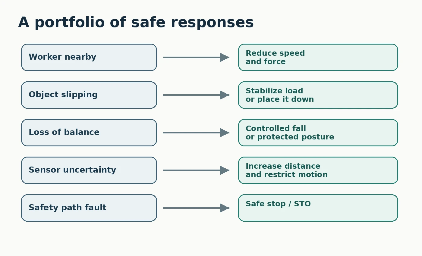
The safety response hierarchy
A practical architecture separates responses by severity, controllability, and assurance. At the lowest level, the robot can remain operational while reducing exposure: slower motion, lower joint torque, increased separation distance, restricted reach, or a narrower task envelope. A second level preserves a limited function needed to prevent harm, such as stabilizing a load, maintaining balance, supporting a person, or moving to a protected posture. A third level performs a controlled stop or controlled energy reduction. The final level invokes hard protective action such as STO, brake engagement, branch power isolation, or an emergency stop.
This hierarchy is not a license for unlimited adaptive behavior. Each response must have defined entry conditions, maximum execution time, monitored parameters, fault reactions, and a known fallback. The transition itself is part of the safety function. A “safe pose” that takes too long to reach, relies on an unavailable sensor, or passes through a hazardous trajectory is not safe merely because the final posture is benign.
| Situation | Preferred response | Required assurance | Fallback |
|---|---|---|---|
| Person enters extended protective zone | Reduce speed and force; increase separation | Validated detection, bounded motion, monitored speed | Controlled stop |
| Object begins slipping | Stabilize, lower, or place object in a defined area | Grip, force, trajectory, and human-presence monitoring | Protected release or stop |
| Biped loses stability | Recover balance or choose a protected fall posture | Independent inertial and joint-state monitoring | Energy reduction and post-impact isolation |
| Perception confidence falls | Expand margins and restrict autonomous motion | Confidence monitoring and plausibility checks | Safe halt |
| Safety-controller fault | Execute hardware-backed protective action | Independent diagnostics and final elements | STO, brakes, power isolation |
AI-assisted safety without AI becoming the sole safety authority
AI can materially improve safety because many humanoid hazards are contextual. Learned perception can identify people, body posture, tools, unstable objects, floor conditions, blocked escape routes, and unusual behavior. Prediction models can estimate trajectories and time-to-collision. Anomaly detection can expose sensor drift, actuator degradation, or behavior outside the validated distribution. Generative and simulation-based tools can also support hazard analysis, test generation, scenario coverage, and safety-case maintenance.
The critical distinction is between assistance and authority. An AI model may propose that the robot slow, yield, reposition, or stop. The assured safety path must determine whether the proposal is permissible inside a validated safety envelope. This path should use bounded inputs, deterministic checks, independent monitoring, and a defined fallback. Where an AI component itself performs a safety function, the assurance burden expands to data governance, model-change control, robustness, human oversight, traceability, and lifecycle monitoring. The EU AI Act makes this convergence explicit for high-risk AI that serves as a safety component of regulated products (Reference 08 – Artificial Intelligence Act).
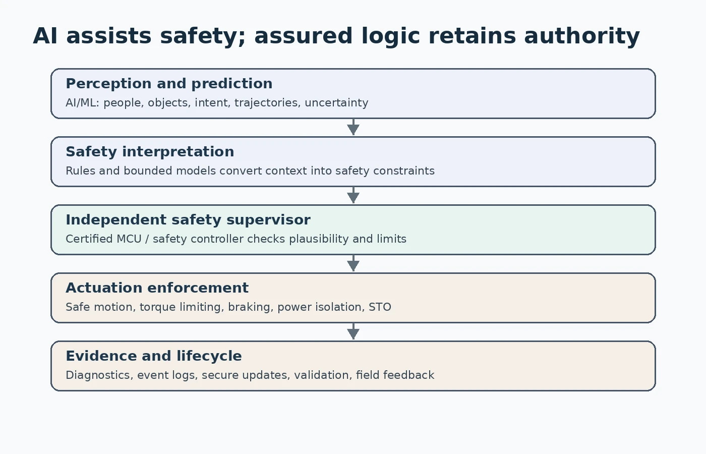
A bounded safety contract
A useful design pattern is a safety contract between the autonomy stack and the safety supervisor. The autonomy system publishes a proposed action, estimated uncertainty, and relevant context. The safety supervisor publishes hard constraints: maximum speed, torque, kinetic energy, reachable volume, minimum separation, allowed contact mode, braking reserve, and permitted recovery actions. The safety supervisor does not need to understand every semantic detail of the task. It must reliably enforce the physical limits that keep the task inside the validated envelope.
This approach allows sophisticated behavior without making the safety case depend entirely on the correctness of a large perception or foundation model. It also supports graceful degradation. When uncertainty rises, the envelope contracts. When a sensor is lost, the robot can switch to a restricted mode that relies on remaining independent channels. When the safety path itself is compromised, the system moves to the strongest available protective state.
Context awareness must include the robot’s own physical state
Situational awareness is often described as external perception, but a humanoid’s internal state is equally important. Safe behavior depends on battery state, thermal headroom, brake availability, joint backlash, actuator saturation, network latency, compute health, sensor synchronization, and the robot’s dynamic stability margin. A robot that appears stationary can still be hazardous if its joints are storing gravitational or elastic energy. A low battery can reduce the ability to complete a stabilizing movement. Thermal derating can lengthen stopping distance. Lost time synchronization can corrupt the apparent relationship between a person and a moving limb.
The safety model must therefore combine exteroception, proprioception, energy state, and system health. This is where semiconductor implementation becomes decisive: the robot requires independent sensing, diagnostic coverage, predictable control, protected communication, and final actuation mechanisms that remain effective when the primary AI computer is faulty or unavailable.
Functional safety remains the assurance backbone
Situational safety is an extension of functional-safety engineering, not a replacement. IEC 61508 establishes the lifecycle logic for electrical, electronic, and programmable safety-related systems: identify hazards, specify safety functions, assign integrity requirements, control systematic failures, quantify random hardware failures, verify implementation, validate the complete function, and manage change throughout operation (Reference 05 – IEC 61508). ISO 13849-1:2023 provides a machinery-oriented methodology for safety-related parts of control systems and their performance levels (Reference 04 – ISO 13849-1:2023). IEC 62061 provides a complementary SIL-based machinery route (Reference 12 – IEC 62061:2021).
The 2025 revisions of ISO 10218-1 and ISO 10218-2 modernize the industrial-robot baseline at robot and application level (Reference 01 – ISO 10218-1:2025) and (Reference 02 – ISO 10218-2:2025). They do not by themselves solve every safety question posed by general-purpose humanoids, but they strengthen the vocabulary and architecture from which industrial deployments will be assessed. (Reference 11 – ISO 13482) provides an established human-facing robot baseline, while ISO’s work on industrial mobile robots with actively controlled stability is especially consequential because it directly addresses robots that can become unstable without active control, including bipedal and quadrupedal forms (Reference 03 – ISO/CD 25785-1).
The unresolved challenge is dynamic decision assurance. Existing standards are strongest when a safety function and its triggering conditions can be specified in advance. Humanoids expand the number of contexts and transitions. The engineering response should not be to declare an open-ended “intelligent safety” function. It should decompose behavior into testable safety functions: safe limited speed, safe joint torque, safe protective separation, safe load stabilization, safe balance recovery, safe fall mitigation, safe energy isolation, safe manual recovery, and safe restart.
Cybersecurity is part of the safety argument
A connected humanoid can be functionally correct and still unsafe if an attacker can alter sensor data, motion limits, safety parameters, update images, time synchronization, or operator commands. Safety and security therefore share assets, failure effects, and lifecycle processes. The safety analysis must consider malicious causes for hazardous behavior, while the security analysis must prioritize attacks capable of defeating risk-reduction functions.
IEC 62443-4-1 defines secure product-development lifecycle requirements including security requirements, secure design and implementation, verification, vulnerability handling, patch management, and end-of-life processes (Reference 06 – IEC 62443-4-1). The EU Cyber Resilience Act adds horizontal obligations for products with digital elements, including vulnerability handling and secure lifecycle support (Reference 09 – Cyber Resilience Act). The Machinery Regulation explicitly addresses safety effects arising from software and cybersecurity and becomes the central EU machinery framework from 20 January 2027 (Reference 07 – Machinery Regulation).
For the robot architecture, this means secure boot, authenticated firmware, protected safety configuration, hardware-backed keys, signed updates, rollback protection, secure debug, domain separation, authenticated communication, monotonic event logs, and a recovery path that does not depend on a compromised cloud service. Safety-critical updates require controlled impact analysis and revalidation. A remotely updated perception model must not silently change the assumptions under which a safety envelope was validated.
Semiconductors turn the safety concept into enforceable physics
The safety architecture is realized through sensing, compute, connectivity, motor control, power management, and security devices. Safety-capable microcontrollers can supervise the non-safety compute stack using lockstep cores, memory protection, clock and voltage monitors, watchdogs, error-correcting memory, redundant peripherals, and hardware safety management. Independent current, position, torque, and inertial sensing enables plausibility checks. Motor-control devices and gate drivers enforce torque and switching constraints. Brakes, e-fuses, high-side switches, and power-distribution devices provide final protective action. Hardware security modules protect identity, keys, boot integrity, and update authorization.
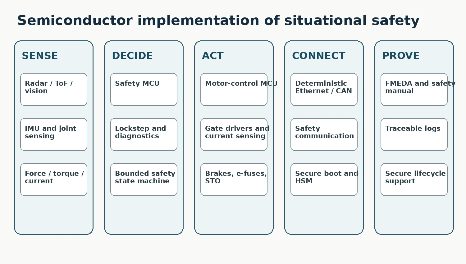
A credible semiconductor safety proposition therefore extends beyond “ASIL-rated” or “safety-ready” parts. Robot developers need safety manuals, FMEDA data, diagnostic assumptions, failure-rate information, reference architectures, example safety mechanisms, tool qualification guidance, cybersecurity documentation, and integration support. The system safety case must show that the selected devices, software, mechanics, and operating assumptions collectively achieve the required risk reduction.
Distributed safety for a distributed body
A humanoid contains many joints and local control loops. Routing every protective decision through one central computer creates latency, bandwidth, and common-cause concerns. A more resilient design distributes enforcement: local joint controllers monitor torque, current, position, velocity, temperature, and communication freshness; regional controllers supervise limbs and power domains; a central safety supervisor coordinates robot-level constraints and operating modes. The architecture must still define independence, synchronization, fault containment, and final authority. Distribution is useful only when it reduces—not obscures—the safety argument.
Regulation is converging on lifecycle accountability
The regulatory direction is clear even though humanoid-specific rules remain incomplete. Manufacturers must increasingly demonstrate not only that a robot was safe when placed on the market, but that software changes, AI updates, cyber vulnerabilities, and substantial modifications are controlled throughout the product lifecycle. The Machinery Regulation, AI Act, and Cyber Resilience Act create overlapping obligations around risk management, technical documentation, post-market monitoring, incident handling, software integrity, and change control.
This convergence has a practical consequence: the robot’s safety case can no longer be a static certification artifact. It must be a maintained engineering system linked to requirements, architectures, test evidence, software versions, model versions, field incidents, vulnerability records, and approved operating envelopes. AI-assisted tools may help maintain that evidence, but accountability remains with the responsible organizations and named engineering roles.
The role of the system architect for functional safety
The system architect for functional safety—often abbreviated SAR FuSa in development organizations—must translate changing robot behavior into stable safety requirements. The role spans mechanics, electronics, embedded software, AI, cybersecurity, power, communications, and deployment. Its central task is to prevent local optimization from weakening the system-level safety argument.
For situational safety, the architect must define the response portfolio, identify which context variables are safety-relevant, allocate functions to independent channels, specify degraded modes, manage assumptions about AI and perception, and ensure that every transition has a validated fallback. The architect also needs authority over change control. A new grasping model, faster joint controller, battery variant, wireless interface, or fleet update mechanism can alter stopping behavior, thermal limits, fault latency, or foreseeable misuse.
Engineering principles for the next generation
First, define safety by risk reduction, not by motion cessation. Stopping remains essential, but it is one response among several. Second, separate contextual intelligence from assured enforcement. AI may improve interpretation; bounded safety logic must retain authority over physical limits. Third, design graceful degradation explicitly. Reduced capability should be a validated operating mode, not an improvised reaction. Fourth, treat cybersecurity faults as potential safety causes. Safety parameters, updates, identity, time, and communication integrity belong in the hazard analysis. Fifth, build the lifecycle evidence from the beginning. Diagnostics, logs, traceability, safety documentation, and update governance are architecture requirements, not post-design paperwork.
Conclusion: the safest robot is not always the one that stops
Humanoid robots move safety engineering from a fixed machine state toward a controlled decision about the least hazardous achievable state. That decision must consider people, task, environment, load, stability, energy, uncertainty, and system health. It may require slowing, yielding, stabilizing, repositioning, lowering a load, adopting a protected posture, performing a controlled stop, or isolating torque and power.
The opportunity is not to replace functional safety with artificial intelligence. It is to use context and prediction to choose among pre-engineered, independently supervised, and physically enforceable safety responses. The result is a robot that can remain useful without becoming reckless, and can become safe without blindly surrendering control at the moment control is most needed.
Glossary
- Failure Modes, Effects and Diagnostic Analysis
A quantitative analysis used to classify failure modes, estimate diagnostic coverage, and support functional-safety hardware metrics.
- Functional safety
The part of overall safety that depends on a system or equipment operating correctly in response to its inputs, including detected faults.
- Graceful degradation
Controlled reduction of capability while preserving validated safe functionality rather than immediately losing all robot function.
- Hardware Security Module
A protected hardware subsystem that performs and safeguards cryptographic operations, keys, secure boot, authentication, and trusted services.
- Performance Level
A discrete level under ISO 13849 expressing the ability of safety-related control-system parts to perform a safety function under foreseeable conditions.
- Safe state
A system condition in which residual risk is reduced to an acceptable level for a defined hazard and operating context; it is not necessarily power-off.
- Safe Torque Off
A drive safety function that prevents torque-producing energy from being applied to a motor, without necessarily removing all electrical power.
- Safety envelope
The bounded set of permissible speeds, forces, trajectories, distances, energies, and operating modes for a given assessed context.
- Safety Integrity Level
A discrete level used to specify the required integrity of a safety function implemented by electrical, electronic, or programmable electronic systems.
- Situational safety
A safety approach that selects a validated risk-reduction response according to the robot’s current task, environment, human proximity, physical state, and uncertainty.
References
- IEC 61508 — Functional safety of E/E/PE safety-related systems. Establishes risk-based functional-safety lifecycle principles, safety functions, integrity levels, systematic capability, diagnostics, verification, and validation. Source
- IEC 62061:2021 — Safety of machinery — Functional safety of safety-related control systems. Applies functional-safety lifecycle and SIL concepts to machinery control systems using electrical, electronic, and programmable electronic technologies. Source
- IEC 62443-4-1:2018 — Secure product development lifecycle requirements. Defines secure development lifecycle requirements covering security specification, design, implementation, verification, defect handling, patching, and end-of-life. Source
- ISO 10218-1:2025 — Robotics — Safety requirements — Part 1: Industrial robots. Defines inherently safe industrial robot design, risk reduction measures, safety functions, and information needed before integration into applications. Source
- ISO 10218-2:2025 — Robotics — Safety requirements — Part 2: Industrial robot applications and robot cells. Updates system-integration safety requirements for industrial robot applications, including collaborative operation and application-level risk reduction measures. Source
- ISO 12100:2010 — Safety of machinery — General principles for design. Provides the foundational machinery risk-assessment and risk-reduction framework used to identify hazards and select protective measures across lifecycle stages. Source
- ISO 13482:2014 — Robots and robotic devices — Safety requirements for personal care robots. Covers personal-care robot hazards including mobility, stability, contact, control failures, electrical risks, and human-facing service environments. Source
- ISO 13849-1:2023 — Safety of machinery — Safety-related parts of control systems. Provides methodology for designing and integrating safety-related control-system parts, including software, using required performance levels and architectures. Source
- ISO/CD 25785-1 — Robotics — Safety requirements for industrial mobile robots with actively controlled stability. Addresses bipedal, quadrupedal, and balancing mobile robots that require active control to remain stable in industrial environments. Source
- Regulation (EU) 2023/1230 on machinery. Modernizes EU machinery law, addressing software, AI-related safety functions, cybersecurity effects, substantial modification, and digital technical documentation. Source
- Regulation (EU) 2024/1689 — Artificial Intelligence Act. Establishes risk-based AI obligations; safety components of regulated products can qualify as high-risk AI requiring integrated conformity processes. Source
- Regulation (EU) 2024/2847 — Cyber Resilience Act. Sets horizontal cybersecurity requirements for products with digital elements, including vulnerability handling, secure updates, and lifecycle manufacturer obligations. Source