Foundations of Embodied Intelligence
Chapter 13
Power Integrity Is Robot Intelligence
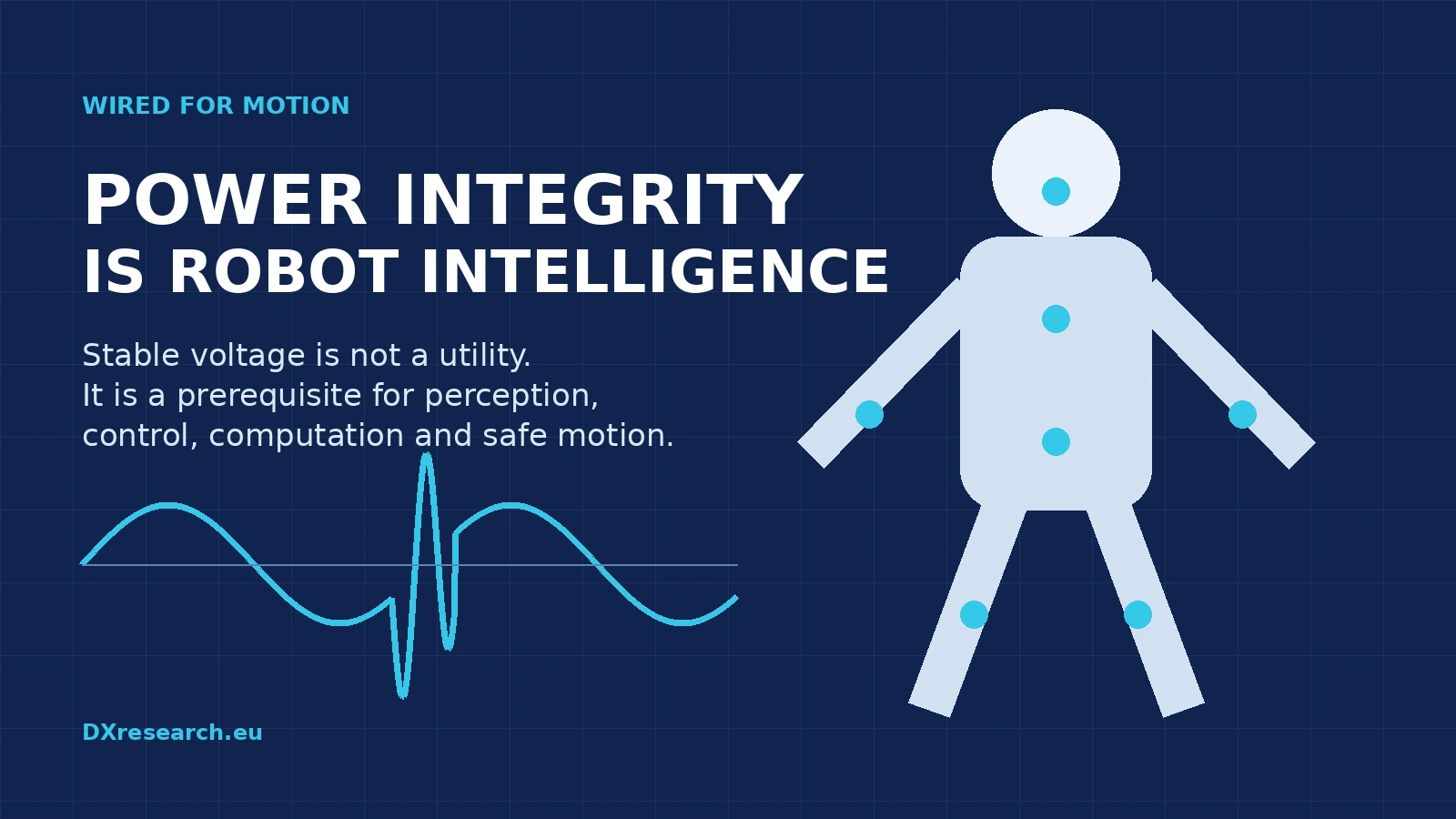
The central thesis of this chapter is that power integrity is a form of embodied intelligence. A robot remains intelligent only while its sensors preserve signal quality, its processors retain state, its communications stay deterministic, and its actuators receive controlled energy. These conditions depend on the power-delivery network as much as on algorithms. The design problem is therefore not simply how many watt-hours the battery stores. It is whether the system can deliver and recover power at the location, voltage, current, noise level, and time scale demanded by each physical event.
This framing adds a distinct layer to discussions of battery capacity and thermal management. Energy capacity determines how long a robot might operate under an assumed profile; thermal design determines how much loss can be tolerated. Power integrity determines whether the robot can execute the profile at all, especially during the brief events that define balance, contact, recovery, and safe shutdown. Current humanoid system maps already treat battery management, power distribution, motor control, compute, sensing, connectivity, safety, and security as coupled domains rather than isolated boards (Reference 1 – Humanoid Robots; Reference 2 – Humanoid Robots Application Presentation).
The Robot Is a Moving Transient Generator
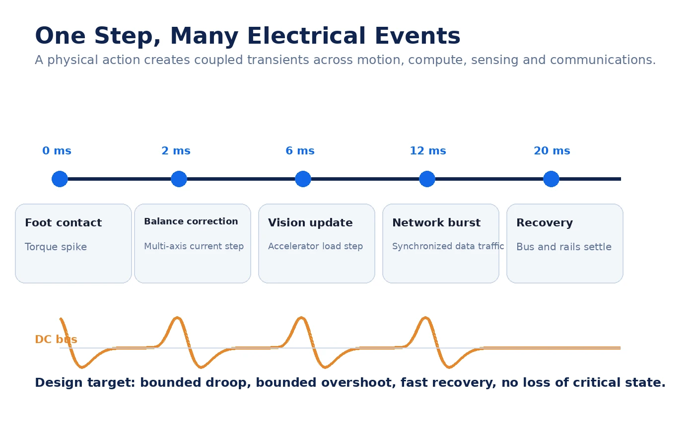
Conventional energy calculations often begin with average power. Average power is useful for battery runtime, cooling, and mission planning, but it hides the events that cause resets, corrupted measurements, nuisance protection trips, and accelerated component aging. A humanoid may move from quiet standing to balance recovery in milliseconds. Several joints can demand peak torque together while a perception accelerator starts a new inference cycle and a radio or Ethernet interface transmits synchronized data. The battery sees a composite load, but each local rail experiences a different waveform.
A load transient tests the closed-loop response of a converter and the impedance of the complete path feeding it. Abrupt current changes can create droop, overshoot, or ringing; transient testing is specifically used to reveal whether the regulator returns to its target without sustained oscillation (Reference 6 – Line and Load Transient Testing). The same principle applies from a sub-volt processor core to a tens-of-volts actuator bus. The amplitudes differ, but the engineering question is identical: how far does the rail depart from its permitted envelope, for how long, and what state is lost during the excursion?
Mechanical events become electrical events
Foot contact is not merely a mechanical shock. It produces a torque correction, which produces a current step, which produces a voltage disturbance and electromagnetic emission. A rapid arm stop can create regenerative braking, raising the DC-link voltage if recovered energy has nowhere to go. A fall-arrest maneuver can simultaneously demand high joint current and reliable perception. Motor-drive design therefore requires more than nominal current matching. Payload, motor power, switching devices, gate-drive strength, switching speed, current sensing, and thermal behavior must be evaluated as one chain (Reference 5 – Relating Payload to Motor Driver Requirements).
Verified engineering practice from servo drives is directly relevant. A protected nominal 48 V bus can require reverse-polarity protection, overcurrent control, inrush limiting, reverse-current blocking, and tolerance of much higher transients (Reference 3 – Protected DC Bus Reference Design). This does not establish 48 V as the universal humanoid voltage. It establishes a durable architectural principle: a mobile multi-axis machine must treat its shared bus as a fault domain with explicit boundaries, not as an ideal source.
Four Time Scales, One Power Architecture
A humanoid power system operates across at least four time scales. Nanosecond-to-microsecond behavior is dominated by switching edges, package parasitics, decoupling, gate drive, and electromagnetic compatibility. Microsecond-to-millisecond behavior includes converter control loops and local load steps. Millisecond-to-second behavior includes multi-axis motion, compute bursts, contactor operation, and protection decisions. Minute-to-hour behavior includes battery state estimation, thermal drift, mission scheduling, charging, and degradation.
| Time scale | Typical event | Primary risk | Semiconductor response |
|---|---|---|---|
| ns–µs | Switching edge, commutation, digital current spike | Noise, overshoot, false sensing, device stress | Package choice, gate control, layout, local decoupling, filtering |
| µs–ms | Processor or actuator load step | Rail droop, ringing, reset, loss of control margin | Fast regulators, multiphase conversion, telemetry, compensation |
| ms–s | Balance recovery, coordinated lift, regeneration | Bus collapse or rise, protection trip, torque clipping | DC-link storage, current limiting, braking path, zonal arbitration |
| min–h | Mission, charge, thermal drift, aging | Reduced available power, runtime shortfall, accelerated wear | BMS estimation, thermal sensing, power-aware scheduling, diagnostics |
These scales cannot be optimized independently. Large local capacitors can reduce a fast droop but increase inrush. Aggressive current limiting can protect switches but destabilize a balance controller if torque disappears without warning. Faster switching can reduce magnetic size but increase common-mode emissions. Higher bus voltage can reduce conductor current for a given power but raises insulation, clearance, protection, and switching requirements. Good architecture does not eliminate trade-offs; it makes them visible and assigns them to controlled interfaces.
Compute is now a dynamic electromechanical load
AI accelerators introduce power-delivery challenges familiar from high-performance computing into a physically mobile system. Accelerator cards can exhibit severe transient demands caused by changing compute utilization and data movement; multiphase conversion and power-distribution impedance become performance constraints rather than peripheral concerns (Reference 7 – AI Accelerator Power Delivery). In a humanoid, the resulting droop is not confined to a server board. It may coincide with a motor event and alter perception latency precisely when the robot must recover balance.
This creates a design need for power-aware computing. An inference scheduler should know whether electrical headroom is available, just as a motion planner should know torque and thermal limits. The interpretation is broader than dynamic voltage and frequency scaling. It means coordinating compute modes, sensor activation, communications, and motion so that the robot avoids creating electrical peaks that add little task value. The scheduler does not replace robust hardware; it uses hardware telemetry to remain inside a validated operating envelope.
Architecture: From One Battery to Many Controlled Domains
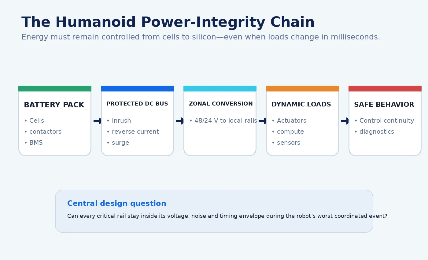
The battery is the robot’s energy source, but it should not be the instantaneous source for every load. A strong architecture inserts layers of protection, conversion, buffering, measurement, and control. The battery management system protects cells and estimates state. A protected high-energy bus distributes power efficiently. Zonal converters create local intermediate rails. Point-of-load converters generate tightly regulated supplies near processors, sensors, and communications devices. Local capacitors and, where justified, other storage elements handle the fastest events.
The architecture should estimate not only state of charge but also state of power: how much power the battery can safely deliver or absorb over a stated interval under present temperature, state of charge, aging, and cell imbalance. A pack can contain substantial energy yet be unable to support a peak without excessive droop. Conversely, a nearly charged pack may have limited ability to absorb regeneration. Treating available power as a dynamic system variable links the BMS to motion planning and protection.
Centralized versus zonal conversion
A centralized design can reduce converter count and simplify some monitoring, but it lengthens low-voltage high-current paths and can couple distant loads through shared impedance. Zonal conversion moves regulation closer to actuators and electronics, reducing conductor current on local low-voltage rails and enabling fault isolation. It also increases the number of converters, control interfaces, and thermal nodes. The likely industrial direction is not purely centralized or purely distributed; it is hierarchical. High-energy distribution remains centralized enough to manage the battery and major contactors, while conversion and protection become increasingly zonal.
Semiconductor integration is decisive in making this hierarchy practical. Power MOSFETs, gate drivers, current sensors, microcontrollers, PMICs, isolated transceivers, secure elements, and protection ICs determine the size and observability of each zone. Integrated motor-control solutions are already positioned as a route to scalable, precise, and efficient humanoid motion (Reference 12 – Infineon and NVIDIA Motor-Control Collaboration). Yet integration must preserve diagnosability. A compact module that cannot expose current, voltage, temperature, fault history, and timing information may save board area while weakening system assurance.
Protection Must Be Selective, Predictable, and Observable
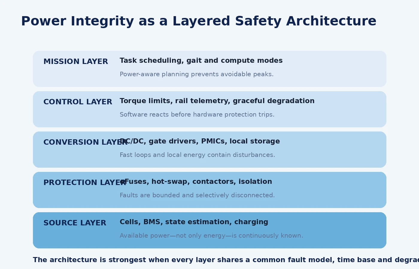
Protection is often described as a list of thresholds: overvoltage, undervoltage, overcurrent, short circuit, reverse polarity, overtemperature. A humanoid requires more. It needs selective protection: the ability to isolate the failing branch while keeping healthy and safety-critical functions alive. If a finger actuator shorts, the robot should not necessarily lose perception, communication, and balance control. If a compute rail fails, the system may still need an independent safety controller and controlled energy for braking or kneeling.
Electronic fuses and hot-swap controllers can limit inrush, monitor current, and disconnect faulty branches. Integrated protection devices combine several functions, including voltage, current, reverse-condition, and thermal control (Reference 9 – Complete System Power Protection Design Guide). Their settings must be coordinated with downstream converter startup, motor stall behavior, wiring impedance, and the safe operating area of switching devices. A threshold that is safe for silicon but too fast for the mechanical control strategy can still create a hazardous robot response.
Graceful degradation is an electrical behavior
Graceful degradation requires reserved power and deterministic priority. The robot may reduce walking speed, cap joint torque, disable nonessential perception channels, lower compute performance, or reject a new task while preserving stabilization, communications, diagnostics, and controlled shutdown. Such behavior is only credible if the power architecture supports separate domains and exposes trustworthy telemetry. A monolithic rail with opaque protection cannot deliver nuanced degradation; it can only remain on or switch off.
This changes the relationship between functional safety and power design. Power is not merely a cause of random hardware failure. It is also the mechanism through which the system preserves or loses authority. Safety analysis should therefore include power-domain dependencies, brownout behavior, restart ordering, latent protection faults, regenerative overvoltage, sensor-reference shifts, and the consequences of partial isolation. The safe state of a mobile robot may require active energy for several seconds, so the architecture must guarantee that energy under the relevant fault assumptions.
Control-Loop Stability Extends Beyond the Converter
A regulator may be stable on a bench and still behave poorly in the robot because its source impedance, cable inductance, input filter, downstream converters, operating modes, and digital control policies differ from the test condition. Converter phase margin and bandwidth are directly related to load-transient response and damping (Reference 8 – Power Supply Loop Stability). In a distributed robot, several regulated stages can interact. Constant-power loads can present negative incremental impedance, while current-limited motor drives can abruptly change system dynamics.
The engineering response is impedance-based verification across operating conditions, not only component-level efficiency measurement. Designers should characterize source and load impedance, startup sequences, mode transitions, regenerative events, and fault recovery. Hardware-in-the-loop testing should reproduce coordinated mechanical and computational loads. The worst electrical case may not be maximum torque or maximum compute alone; it may be a specific temporal alignment of moderate events.
Signal integrity and power integrity converge
Voltage disturbance changes more than supply margin. It can shift sensor references, increase clock jitter, corrupt analog measurements, raise bit-error rates, and trigger false diagnostics. Fast motor switching produces differential and common-mode noise that can couple into encoders, cameras, force sensors, and communication links. Isolation, grounding, return-path design, shielding, slew-rate control, and synchronized sampling therefore belong to the power-integrity discipline.
This convergence matters for machine learning because corrupted observations may remain numerically plausible. A processor reset is obvious; a biased force measurement or sporadic encoder error can be interpreted as the environment. Power and electromagnetic disturbances can therefore become data-quality faults. The robust architecture detects them through redundant sensing, rail telemetry, plausibility checks, timestamp correlation, and fault logging.
Efficiency Is Necessary but Not Sufficient
High efficiency reduces battery drain and heat, but a converter optimized only for its peak efficiency point may respond poorly to dynamic loads or light-load transitions. Similarly, a motor sized for extreme performance may operate inefficiently during ordinary walking or standing. Recent humanoid research and field reporting continue to show that leg architecture, motor sizing, gait, and operating regime strongly influence energy consumption (Reference 10 – Energy-Efficient Humanoid Leg; Reference 11 – Marathon-Winning Humanoid Robots).
The durable interpretation is that robot efficiency is a system property. Semiconductor conduction and switching losses matter, but so do motor operating points, transmission ratio, mechanical compliance, gait planning, bus voltage, regeneration, compute scheduling, and auxiliary loads. A design that improves one efficiency number while increasing mass, EMI filtering, or control complexity can lose at system level. The correct metric set includes task energy, peak power, transient margin, thermal headroom, fault containment, and useful work per charge.
| Optimization target | What it improves | What it can accidentally worsen |
|---|---|---|
| Higher bus voltage | Lower current and conductor loss | Insulation, switching stress, EMI, protection complexity |
| Faster switching | Smaller magnetics and faster control | Switching loss, common-mode noise, layout sensitivity |
| Larger bulk capacitance | Transient buffering and regeneration absorption | Mass, volume, inrush, stored fault energy |
| Tighter current limits | Device and wiring protection | Unexpected torque clipping and control instability |
| More integration | Size, assembly, parasitics | Thermal concentration and reduced repairability |
A Verification Program for Embodied Power
Power-integrity verification should begin with mission profiles and fault scenarios rather than a single maximum-current specification. Engineers can derive representative electrical events from walking, lifting, kneeling, recovering balance, grasping, charging, and emergency stopping. Each event should define expected current waveforms, permissible rail deviation, recovery time, thermal state, and required retained functions.
Motor stages must be tested at stall, rapid reversal, regeneration, and repeated peak loading. High-current motor-drive reference designs demonstrate why cycle-by-cycle current protection and explicit stall behavior are important (Reference 4 – 36 V, 1 kW BLDC Motor Drive). Compute rails require workload-based transients, not static electronic loads alone. Sensors should be evaluated while neighboring actuators switch. Protection should be tested with realistic harness impedance and failure location.
A credible program records voltage, current, temperature, clock, communication errors, control-state transitions, and mechanical response on a shared time base. This allows engineers to determine causality: whether a torque disturbance caused a bus event, whether the bus event delayed perception, and whether the delayed perception amplified the motion. The result is an electrical digital thread connecting semiconductor behavior to robot behavior.
Design rules that survive platform change
Specific bus voltages, converter topologies, battery chemistries, and processor choices will change. Several principles remain stable:
- Design from worst coordinated events, not the sum of nameplate ratings or average power.
- Keep high-energy distribution protected and observable; move tightly regulated conversion near dynamic loads.
- Reserve energy and independent control for stabilization, diagnostics, communications, and controlled shutdown.
- Coordinate hardware thresholds with mechanical and software degradation policies.
- Measure available power continuously and expose it to motion and compute scheduling.
- Validate disturbances across electrical, computational, sensing, communication, and mechanical domains.
- Treat every protection trip and brownout as a system event with persistent diagnostic evidence.
Conclusion: Stable Voltage Creates Trustworthy Agency
A humanoid robot converts electrical energy into physical agency. The quality of that conversion is not captured by battery capacity, motor torque, processor throughput, or converter efficiency in isolation. It is captured by whether the robot can preserve controlled behavior while its internal loads change rapidly and faults appear unpredictably.
Power integrity therefore belongs beside perception, control, safety, cybersecurity, and thermal management as a first-order architecture. It defines how energy is distributed, how disturbances are contained, how subsystems reveal their state, and how the robot degrades when full performance is no longer available. Semiconductors make this architecture possible through efficient switching, precise sensing, fast regulation, protected distribution, deterministic control, secure telemetry, and diagnosable fault containment.
The deepest implication is conceptual: intelligence in a physical machine is not only the ability to choose an action. It is the ability to preserve the electrical conditions under which sensing, reasoning, and action remain trustworthy. Stable voltage is therefore not backstage infrastructure. It is part of the robot’s intelligence.
Glossary
- Battery management system
Electronics and software that monitor cells, estimate battery state, balance cells, control contactors, and enforce operational limits.
- Common-mode noise
Electrical interference appearing in the same direction on multiple conductors relative to a shared reference or chassis.
- DC link
The direct-current electrical bus connecting the battery or converter to distributed motor inverters and auxiliary loads.
- Electronic fuse
A semiconductor protection device that controls inrush and disconnects a load during overcurrent, short-circuit, overvoltage, or thermal faults.
- Graceful degradation
Maintaining bounded, reduced functionality after a fault instead of abruptly losing all operational capability.
- Load transient
A rapid change in current demand that causes temporary voltage deviation and tests the dynamic response of the power system.
- Point-of-load converter
A regulator placed close to the consuming circuit to create a tightly controlled local voltage rail.
- Power integrity
The ability of a power-delivery network to keep voltage, current, noise, timing, and protection behavior within specified limits under static and dynamic conditions.
- Power-aware computing
Compute scheduling and performance control informed by available electrical and thermal capacity rather than processing demand alone.
- Power-delivery network
The complete electrical path from an energy source through protection, distribution, conversion, interconnects, and local decoupling to each load.
- Regenerative braking
Recovery of mechanical energy during deceleration by operating a motor as a generator and returning energy to the bus or storage.
- Safe operating area
The combinations of voltage, current, power, and time over which a semiconductor can operate without damage.
- Selective protection
A fault-containment strategy that isolates only the affected branch while maintaining power to healthy and safety-critical functions.
- State of power
An estimate of the power a battery can safely deliver or absorb over a defined time horizon under present conditions.
References
- 36-V, 1-kW Brushless DC Motor Drive With Stall Current and Speed Control. A motor-drive reference design demonstrates cycle-by-cycle overcurrent protection and high-current power-stage behavior relevant to compact robotic joint actuation. Source
- A Biomimetic and Energy-Efficient Leg Design for a Humanoid Robot. Research article examines an exclusively linear-actuated humanoid leg and frames lower-body design as a central determinant of bipedal energy consumption. Source
- Complete System Power Protection Design Guide. Design guide surveys integrated protection against overvoltage, undervoltage, overcurrent, reverse conditions, and thermal faults in distributed electronic power systems. Source
- Humanoid Robots. Application overview maps motor control, battery management, power distribution, sensing, connectivity, compute, memory, functional safety, and security into humanoid systems. Source
- Humanoid Robots Application Presentation. System presentation identifies battery management, charging, zone control, motor control, sensing, and main compute as interdependent humanoid design domains. Source
- Impacts of Transients on AI Accelerator Card Power Delivery. Analysis shows how accelerator load transients stress power-distribution networks and why multiphase conversion, impedance control, and fast response protect computation. Source
- Infineon to Enable Humanoid Robots with Precise Motion and Efficiency Powered by NVIDIA Technology. Collaboration announcement positions scalable motor control, microcontrollers, safety, security, sensing, and connectivity as foundations for efficient humanoid motion platforms. Source
- Line and Load Transient Testing for Power Supplies. Technical article explains how abrupt line and load changes reveal overshoot, ringing, recovery behavior, and regulator control-loop performance in power supplies. Source
- Protected DC Bus Input Power and Control Power Supply Reference Design for Low-Voltage Servo Drives. Reference design protects a nominal 48-volt servo-drive bus against overvoltage, reverse polarity, overcurrent, inrush, reverse current, and high-voltage transients. Source
- Relating Payload to Brushless DC Motor Driver Requirements. Application note connects mechanical payload requirements with motor power, current, MOSFET sizing, gate-drive control, switching speed, and thermal design choices. Source
- The Secret to Marathon-Winning Humanoid Robots. Reporting on humanoid racing explains how motor sizing, gait choice, mass, heat, and operating regime jointly determine practical energy efficiency. Source
- Understanding Power Supply Loop Stability and Compensation, Part 2. Technical guidance relates converter phase margin and bandwidth to time-domain load-transient response, highlighting the need for stable, sufficiently damped regulation. Source