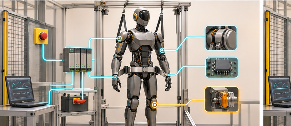
The Safety Function May Be Dormant While Its Risk Is Growing
A humanoid can complete thousands of productive cycles without demanding its last-resort safety mechanisms. The emergency-stop loop remains healthy in appearance because nobody presses it. A gravity-loaded joint brake stays released while the motor holds position. A battery disconnect never interrupts a serious fault. A redundant communication path carries identical traffic but is never forced to assume authority. A watchdog is configured, yet the software path from timeout to physical safe state is not exercised under realistic load.
This creates a specific engineering risk: the robot can accumulate latent dangerous failures inside functions that production data barely observes. Normal uptime may even hide the problem. The better the robot performs, the fewer natural demands occur that would reveal a stuck contact, a degraded brake, a misconfigured alarm reaction or a broken fallback power rail.
Functional-safety practice already distinguishes automatic diagnostics from periodic tests. IEC 62061:2021 introduced requirements for periodic testing, and its 2026 consolidated edition covers the design, integration and validation of safety-related control systems for machinery. ISO 13849-1:2023 provides a methodology for safety-related parts of control systems in high-demand and continuous modes. IEC 61800-5-2 addresses safety-related power-drive systems and diagnostic test intervals for redundant architectures. These foundations are relevant, while their application to a mobile, rechargeable, software-updated humanoid remains architecture- and risk-dependent.
The proposed editorial thesis is measurable. Compare two otherwise similar fleets: one uses configuration-aware proof-test plans and captures physical-response evidence; the other relies on startup self-tests and scheduled maintenance. The first fleet should detect more latent dangerous failures before operational demand, while producing fewer avoidable part replacements and fewer false passes.
Dormancy is not uniform across the robot. A watchdog may be challenged on every boot, while an emergency-stop output contact may remain closed for weeks. One brake may engage at every shutdown, while another is reserved for fault containment. The demand profile is also mission-dependent: a robot carrying parts across a level factory floor presents different gravitational and stopping demands from a humanoid climbing stairs or reaching overhead. Proof-test design must follow the actual demand model instead of treating every safety component as equally exposed.
Safety evidence also decays when the configuration changes. A newly fitted gripper changes inertia. A software update changes acceleration and stop trajectories. A battery replacement changes available fallback energy. A repaired harness can alter diagnostic resistance or routing. The previous result may remain historically true while no longer supporting the current machine. This is why proof-test validity needs a configuration boundary and an expiry rule.
n
The operational exposure window
Consider a joint brake that is normally released while a powered actuator supports a load. The controller may repeatedly confirm that its brake command is available, yet a mechanical change can remain invisible until the brake is required to hold the load. The consequential interval begins when the failure becomes present and ends when a suitable test reveals it or an actual demand exposes it. The interval is an engineering quantity that depends on failure modes, diagnostics, duty cycle and test policy.
Humanoids add moving cable harnesses, vibration, frequent charging and configuration changes to this problem. A safety function can depend on components distributed across joints, battery compartments and controllers. A seemingly small repair may alter the tested chain. The safety record must therefore identify which exact configuration and operating envelope the evidence supports.
Diagnostics and Proof Tests Solve Different Problems
Online diagnostics observe faults during operation. They are strongest when the architecture continuously generates informative signals: lockstep divergence, memory errors, voltage violations, broken wires, communication timeouts or disagreement between redundant sensors. A proof test addresses dangerous failures that automatic diagnostics may not reveal. It deliberately exercises a safety function or subsystem and checks whether the required response still occurs.
The distinction matters because a diagnostic can test its own logic without testing the external effect. A safety microcontroller may correctly assert an emergency output, while a downstream driver is miswired. A drive can acknowledge safe torque off, while a mechanical brake cannot hold the joint. A battery controller can command contactors open, while one contact is welded. The test should extend far enough through the physical chain to support the safety claim.
Proof testing does not mean repeatedly creating a hazardous event. Tests can use controlled energy, fixtures, reduced loads, diagnostic windows and staged actuation. Some can run automatically at boot or shutdown. Others require a service stand, inspection or calibrated measurement. The plan must state what fraction of dangerous failures each test can reveal, which faults remain uncovered and what restoration is required afterward.
Terminology must also be precise. The 2026 consolidated IEC 61800-5-2 removes “proof test” for the power-drive subsystem and retains diagnostic-test concepts because low-demand mode is outside its scope. A complete robot may still contain functions or external elements whose latent failures require periodic testing under the broader machinery safety architecture. The article therefore uses “proof test” at robot and safety-function level, while preserving the terminology of each applicable component standard.
Three layers should therefore be recorded separately. A built-in self-test checks internal electronic mechanisms. A diagnostic test challenges a safety-related subsystem at a defined interval. A robot-level proof test demonstrates that the complete function can still deliver its required physical outcome under controlled conditions. The layers can share equipment and data, yet they provide different evidence. Passing the first cannot automatically substitute for the third.
Coverage is equally important. A brake test performed in one direction may not reveal asymmetric contamination. An emergency-stop test at low speed may confirm the command chain without validating the maximum stopping case. A disconnect test with a discharged bus may not reveal welded contacts under relevant current. Each test record should state the dangerous failure modes it addresses and the assumptions that limit its claim.
n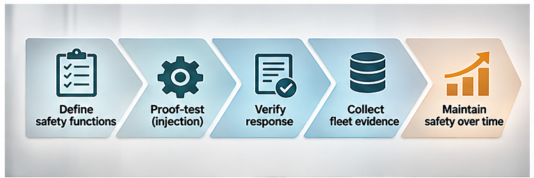
Evidence has a defined boundary
Each test result should identify the stimulus, the measured response, the acceptance criterion, the instrumentation and the conditions under which the result was obtained. A controller log showing that a stop command was issued demonstrates command execution. It does not, by itself, establish stopping distance, contactor separation or the ability of a loaded joint to hold position.
Tests also have side effects. Repeated brake engagement can cause wear, contactor cycling consumes electrical endurance and deliberately removing torque can destabilize a standing biped. The programme must balance fault detection against induced risk and component lifetime. Some functions can be exercised at startup; others require a cradle, restrained posture or a maintenance fixture.
A Humanoid Needs a Safety-Function Test Map
A test map starts with safety functions, not components. Each function is traced from initiating condition through logic, communications, power conversion, actuation and physical outcome. The map records its demand mode, diagnostic coverage, testable failure modes, test interval, safe test conditions and evidence owner.
Representative functions
- Emergency stop: input device, wiring, safe input, logic, communications, drive reaction and motion outcome.
- Safe torque off: command path, gate-driver inhibition, motor-current response and prevention of unintended torque.
- Gravity-load retention: brake control, mechanical holding torque, position drift and controlled release.
- Battery isolation: current reduction, contactor or solid-state disconnect, welded-contact diagnostics and residual voltage.
- Watchdog reaction: fault detection, independent fault signalling, power-stage response and restart control.
- Safety communication: message freshness, corruption detection, channel failover, timing and local fallback.
- Protective sensing: presence, force, speed or separation sensor plausibility through to the commanded safe reaction.
- Fallback power: energy availability for controlled stopping, braking, logging and safe shutdown.
The map should distinguish a function’s logical success from its physical success. It should also identify shared dependencies. A single supply, clock, communication gateway or configuration database may undermine several apparently independent safety mechanisms. Tests that exercise only individual devices can miss these common-cause paths.
Robot configuration changes the map. A wheeled base, heavier payload, replacement arm, new battery, software release or different tool can change stopping time, holding demand, available reserve energy and communication timing. The valid proof-test plan must therefore be linked to the hardware and software configuration that it supports.
The map should include enabling conditions as well as the final reaction. A mechanical brake may require auxiliary power to release safely after the test. A safe communication path may rely on synchronized clocks. A controlled stop may depend on battery headroom to absorb regenerated energy. If the enabling resource is unavailable, a test can appear to reveal a failed safety function even though the real issue is an upstream dependency. Diagnostic sequencing should isolate these causes without hiding the failed end-to-end result.
It should also identify functions that cannot be tested simultaneously. Cutting the main battery may remove the power needed to test communications or record evidence. Exercising a joint brake may conflict with a full-body balance test. The test plan becomes a dependency graph: establish safe support, verify measurement channels, exercise the target function, confirm physical response, restore the system and then test the next dependent function.
n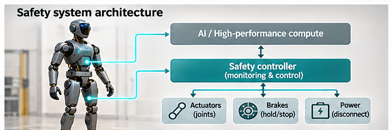
Follow dependencies to the physical endpoint
The test map should make shared power rails, clock sources, communications gateways and measurement paths explicit. Two channels that appear independent at the software interface may rely on the same supply or sensor reference. A test that verifies both using one compromised observer can produce reassuring but correlated evidence.
Each safety function needs a declared safe outcome. For one joint that may mean removing motor torque; for another it may require active balancing before braking. Battery isolation can leave residual energy in capacitors. A successful test should demonstrate the intended physical condition and any permitted transition, not merely the state of a software flag.
Test the Physical Chain, Not Only the Command
The most credible evidence measures the response at the hazard boundary. For emergency stopping, the useful outcome is motion deceleration and final state, not merely a Boolean acknowledgement. For a brake, it is load-holding capability and drift. For electrical isolation, it is current interruption and residual voltage. For a watchdog, it is the complete transition from injected fault to independent reaction.
Physical-response testing brings measurement uncertainty. Encoders can report zero speed while a compliant structure settles. Current sensors have offsets. Brake torque depends on temperature, contamination and load direction. Bus discharge depends on capacitance and connected branches. The test specification should define stimulus, initial state, measurement chain, tolerances, acceptance criteria and uncertainty. Trends can be as valuable as limits: a brake that still passes but loses margin across repeated tests deserves investigation.
Fault injection expands coverage. A safety MCU can emulate alarms, disturb watchdog service, corrupt communications or force sensor disagreement. Infineon documents alarm emulation and self-test mechanisms in the AURIX Safety Management Unit, including fault signalling, configurable reactions and a special mode for testing the SMU itself. These are enabling features. They do not prove that the final robot reaction is safe. The system test must observe the external chain and confirm that configured reactions remain connected to the intended actuators.
Some tests cannot be performed during normal operation. The robot may need a support fixture before brake testing or a bounded area before stopping tests. Service procedures should define these prerequisites and prevent the test mode from escaping into production. A failed or interrupted test leaves the function unproven until the system reaches a defined recovery state.
Test stimuli need their own integrity checks. A simulated overspeed that never reaches the safety monitor proves nothing. A forced watchdog timeout may be masked by a debugger. A communication fault injected above the safety protocol may bypass the mechanism under evaluation. The stimulus path should be observed independently where practical, and its scope documented. Fault injection is evidence only when the injected condition is known to have reached the intended boundary.
Restoration deserves the same rigor as activation. A robot can pass the stop test and remain unsafe because a bypass, service flag or temporary parameter stays active. The procedure should verify that normal parameters, redundancy, fault latches, clocks, network memberships and mechanical supports have returned to the approved configuration. Production authority should remain blocked until restoration evidence is complete.
n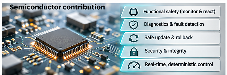
Schedule Tests by Risk, Opportunity and Configuratio
A fixed annual test is simple to administer and often poorly matched to a robot fleet. Some safety paths are exercised naturally every day. Others remain dormant for months. Some components age by time, others by cycles, temperature, vibration, contamination or software change. A risk-based schedule combines maximum intervals with event-driven triggers and convenient operational windows.
Useful triggers include commissioning, battery or actuator replacement, safety-software update, collision, overtemperature, unexpected shutdown, transport, long storage, abnormal diagnostic trend and return from repair. A robot can run lightweight tests at every startup, deeper tests during charging, and mechanically demanding tests in a service fixture. The schedule should never extend beyond the assumptions used in the safety calculation or the manufacturer’s instructions.
The economic goal is coverage with minimal disruption. Test grouping can reduce downtime: a charging session may verify battery isolation, fallback energy, watchdog paths and event logging in one controlled sequence. Fleet orchestration can stagger tests so that operations retain sufficient robot capacity. A missed test becomes an explicit state that can restrict mission authority, rather than a silent maintenance backlog.
Adaptive scheduling is plausible, but it needs boundaries. Field evidence may justify bringing a test forward when drift increases. Extending a certified interval is a stronger claim and requires engineering evidence, change control and alignment with applicable standards and component documentation. An AI model may prioritize inspections; it should not autonomously relax the validated test obligation.
Usage counters can complement calendar time. Relevant measures include emergency-stop channel operations, brake engagements, thermal cycles, high-torque events, charging cycles, connector disturbances, software restarts and transport shocks. Counters should be protected from reset during routine maintenance and interpreted with environmental context. Ten operations at rated load can matter more than thousands of unloaded cycles.
Scheduling policy should define what happens when a test cannot run. The robot may enter a reduced mission set, require supervised operation, return to a service point or stop completely. The response should reflect the safety function and residual risk. An overdue test of a secondary logging channel is not equivalent to an overdue test of gravity-load retention. Transparent graded authority makes the maintenance consequence proportionate and operationally usable.
n
Turn Test Results into Fleet Evidence
A proof-test result should be more than pass or fail. The record should identify the robot, configuration, software and safety parameters; test procedure and version; stimulus; measured response; environmental state; acceptance limits; uncertainty; operator or automated executor; anomalies; restoration checks; and cryptographic integrity where appropriate.
Fleet data can reveal systematic problems that one robot cannot. A rising brake-release time across one production lot may point to contamination or supplier variation. Increased stopping distance after a software update may expose changed torque limits. Repeated watchdog-test failures in one network configuration may reveal a timing dependency. Correlation should remain disciplined: field trends generate hypotheses, while engineering investigation determines cause.
The evidence also improves maintenance economics. A component with demonstrated margin may remain in service within the approved lifecycle strategy. A function with declining margin can be serviced before a hard failure. False failures can be separated from measurement problems when raw signals and test context are retained. The organisation gains a defensible link from safety requirement to deployed performance.
NIST’s robot programmes illustrate the broader value of repeatable test methods and performance metrics: controlled, repeated testing establishes confidence and supports deployment decisions. Proof testing serves a different purpose from capability benchmarking, yet it benefits from the same discipline—defined apparatus, procedures, variables and measurable outcomes.
Fleet evidence needs normalization. Stop time should be associated with speed, payload, posture, floor condition, battery state and temperature. Brake margin should be associated with joint angle, direction and thermal state. Without normalization, a change in mission mix can look like degradation. The evidence system should retain raw measurements and derived features so that future analysis can revisit assumptions.
Statistical analysis should distinguish random variation, gradual drift and step changes. A single borderline result may trigger an immediate safety response while still requiring confirmation of the cause. A fleet-wide step after a software release points toward configuration. A slow change concentrated in one component lot points toward ageing or manufacturing. These interpretations are hypotheses until corroborated, but they help allocate engineering attention efficiently.
n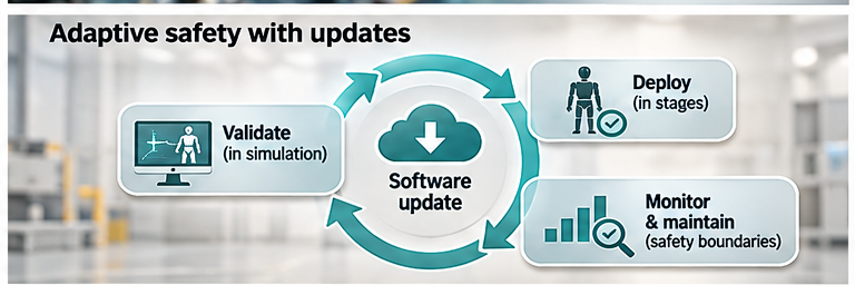
Make trends interpretable
Fleet data is valuable when comparisons account for configuration, usage and environment. A longer stop time might reflect wear, heavier loads, altered floor friction or a software change. Aggregating all robots into one curve can conceal these differences. Engineering review should stratify evidence by hardware revision, software baseline, operating condition and test procedure.
Statistical alerts are useful for identifying investigation candidates, but they cannot independently certify a safety function. Fleet trends can support revised maintenance priorities and test hypotheses. Any change to an acceptance limit needs its own engineering justification and approval.
The Semiconductor Architecture for Testability
Testability begins in the hardware architecture. Safety microcontrollers provide lockstep processing, protected configuration, watchdogs, fault collection, alarm emulation and independent fault signalling. Gate drivers expose diagnostic status and support safe output states. Isolated voltage and current sensors confirm physical energy flow. Position, force and inertial sensors measure motion response. Secure nonvolatile memory preserves test identity and results. Time-aware communications carry safety data with freshness and integrity checks.
Independent paths matter. A self-test executed and evaluated by the same failed element can produce false confidence. Diversity may come from a separate monitor, an external watchdog, an independent sensor, a physical feedback contact or a different diagnostic principle. The appropriate architecture follows the risk assessment and required performance level or safety integrity level.
Semiconductor self-test supports the hierarchy without replacing system testing. Infineon documents continuous comparator self-tests, alarm emulation, fault-signalling protocols and configurable FMEDA support for AURIX devices. Product claims and metrics remain specific to the device and application assumptions. Robot manufacturers must integrate these mechanisms into a complete safety function and validate the external response.
Design-for-test decisions have commercial consequences. Additional sensing, switches, fixtures and memory add cost and mass. Poor testability creates recurring service cost, extended downtime and uncertainty about latent risk. A small diagnostic interface or measurement channel can therefore have lifecycle value far beyond its bill-of-materials cost.
Architects should reserve test access early. Useful provisions include independent measurement points, controllable fault-injection hooks, monitorable safety outputs, safe low-energy test modes, persistent counters and secure test identifiers. Retrofitting them after certification is expensive and can create new interfaces in safety-critical paths. The semiconductor selection process should evaluate diagnostic manuals, safety documentation and supported test mechanisms alongside compute performance and power consumption.
Distributed humanoids also need time coherence. A stop test may combine events from a safety MCU, multiple joint controllers, a power-distribution unit and a fleet computer. Synchronized timestamps and bounded communication latency help reconstruct causality. The safety reaction itself must not depend on cloud timing; the cloud record supports analysis after local mechanisms have acted.
n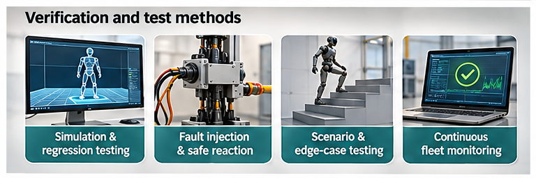
Proof Testing Is Also a Cybersecurity and Governance Problem
A proof-test interface can command stops, disable power, inject faults and enter service modes. Those capabilities create an attack surface. Test authority should be authenticated and role-based. Procedures and acceptance limits need version control. Test mode must be visibly distinct, time-bounded and prevented from enabling unrestricted motion. Results require integrity protection so that a compromised controller cannot simply report success.
Remote fleet operations complicate trust. A cloud service may schedule tests and collect evidence, while the safety reaction remains local. Loss of connectivity must not strand the robot in an ambiguous state. The robot should verify the signed procedure, execute within local safety constraints, preserve the record and reconcile it when communications return.
Software updates are a critical trigger. Changes to motion control, safety parameters, communications, drivers or diagnostic software can alter the validity of previous evidence. The release manifest should identify affected safety functions and required regression or proof tests. A rollback must restore a compatible test baseline. This creates a direct bridge between cybersecurity, configuration management and functional safety.
Governance defines ownership. Engineering specifies coverage and limits. Operations provides test windows. Service restores failed functions. Cybersecurity protects authority and records. Quality analyses fleet trends. The safety case explains how these roles preserve the function through the product lifecycle. Without ownership, proof-test debt becomes invisible until a demand exposes it.
Evidence retention should match the safety and liability context. Records may need to survive controller replacement, while personal or operational data should be minimized. Access controls should separate operators who initiate approved tests from engineers who change procedures and reviewers who approve limits. Auditability is strongest when no single role can silently modify the procedure, acceptance criterion and result.
Secure update design should include negative testing. The robot should reject an expired or configuration-incompatible test package, detect rollback of acceptance limits and preserve the previous evidence when an update fails. Test results should identify the exact signed procedure and configuration. This enables later investigation without assuming that two tests with the same display name were technically identical.
n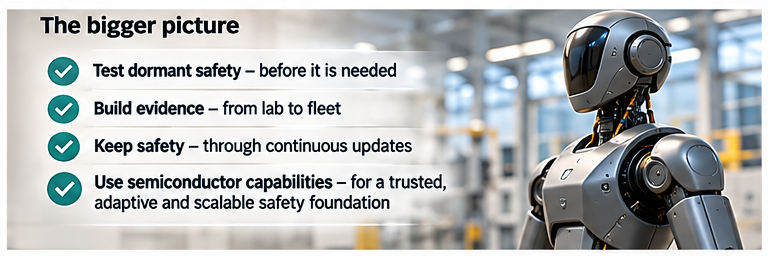
A Deployment Validation Programme
A practical programme starts with a safety-function inventory and fault model. For every function, identify dangerous failures, automatic diagnostics, residual latent faults, physical outcome, test method, interval assumptions and restoration requirements. Review shared dependencies and test-mode hazards.
Bench validation should demonstrate that each injected fault is detected and that the test itself cannot create an uncontrolled hazard. Hardware-in-the-loop testing can cover timing, communication and configuration failures. Robot-level testing should measure physical stopping, holding, isolation and fallback responses across payload, battery, temperature, posture and floor conditions. Environmental and endurance testing should challenge connectors, brakes, sensors and switches over representative lifecycle stress.
Deployment metrics make the thesis falsifiable:
- latent dangerous failures detected before operational demand;
- proof-test coverage by safety function and failure mode;
- overdue tests and mission restrictions;
- false passes, false failures and incomplete restorations;
- test-induced downtime and maintenance hours;
- margin drift in stopping, holding, isolation and fallback performance;
- escaped failures discovered only during a real safety demand.
The open question is how to distribute proof-test responsibility across robot manufacturer, integrator, operator and component supplier. There is no universal interval or single humanoid standard that resolves every deployment. The defensible approach connects risk assessment, applicable standards, component assumptions, field evidence and controlled change.
A phased deployment can make this practical. During engineering pilots, run broad tests frequently and collect raw data. During controlled production deployment, reduce the set to validated high-value tests while preserving event triggers. At fleet scale, monitor coverage, overdue obligations and drift by configuration. Periodically reopen the fault model using field evidence and incident reviews. New capabilities should add explicit test obligations before release.
Acceptance should involve both successful and intentionally unsuccessful cases. The system must pass a healthy test, detect representative failures, refuse operation when evidence is incomplete, and recover cleanly after repair. It should also identify a faulty test fixture or measurement channel. This guards against building a maintenance process that produces reassuring records without dependable discrimination.
Define evidence maturity
Deployment teams can grade each safety function by evidence maturity. At the first level, the function has a documented requirement and component diagnostics. At the second, a controlled subsystem test demonstrates the command and response. At the third, a robot-level test measures the physical outcome across representative operating states. At the fourth, fleet evidence confirms stability, detects drift and links anomalies to configuration. The maturity grade should never be confused with a safety integrity rating; it is a management view of how directly the deployed function has been demonstrated.
This grading exposes gaps without pretending that every function needs the same test depth. A continuously monitored electronic interlock may have strong online coverage and a modest periodic test. A mechanical retention function exposed to contamination and variable load may need direct physical testing. A cloud audit channel may require evidence integrity tests while remaining outside the immediate safety reaction. The safety analysis determines the required claim; the maturity model shows whether the available evidence supports it.
Design the operational handover
After validation, the proof-test programme must become an operating process. The handover should include executable procedures, fixture specifications, calibration needs, expected durations, failure classifications, escalation paths and restoration checks. Operations needs a clear dashboard showing valid, due, failed and overdue tests by robot and safety function. Service teams need diagnostic detail without gaining uncontrolled access to safety parameters.
Suppliers should provide assumptions that make integration possible: diagnostic coverage, permitted test intervals, environmental limits, lifetime limits, safe-state behaviour and the faults that internal diagnostics cannot reveal. Integrators should preserve those assumptions when combining components. Operators should record mission and maintenance conditions that can invalidate them. This chain of evidence is especially important for humanoids assembled from rapidly evolving modules and software stacks.
Finally, incident investigation should feed the test programme. If a real demand reveals a failure that the current tests missed, the response is broader than replacing the component. Engineers should update the fault model, determine why diagnostics and tests lacked coverage, review similar robots and revise the test method under change control. The proof-test architecture becomes a learning system whose purpose is to strengthen safety evidence without allowing the learning algorithm itself to relax validated limits.
A robot’s safety case should therefore include the capability to demonstrate that dormant mechanisms still work. The things a humanoid hopes never to use deserve some of its most disciplined testing.
n