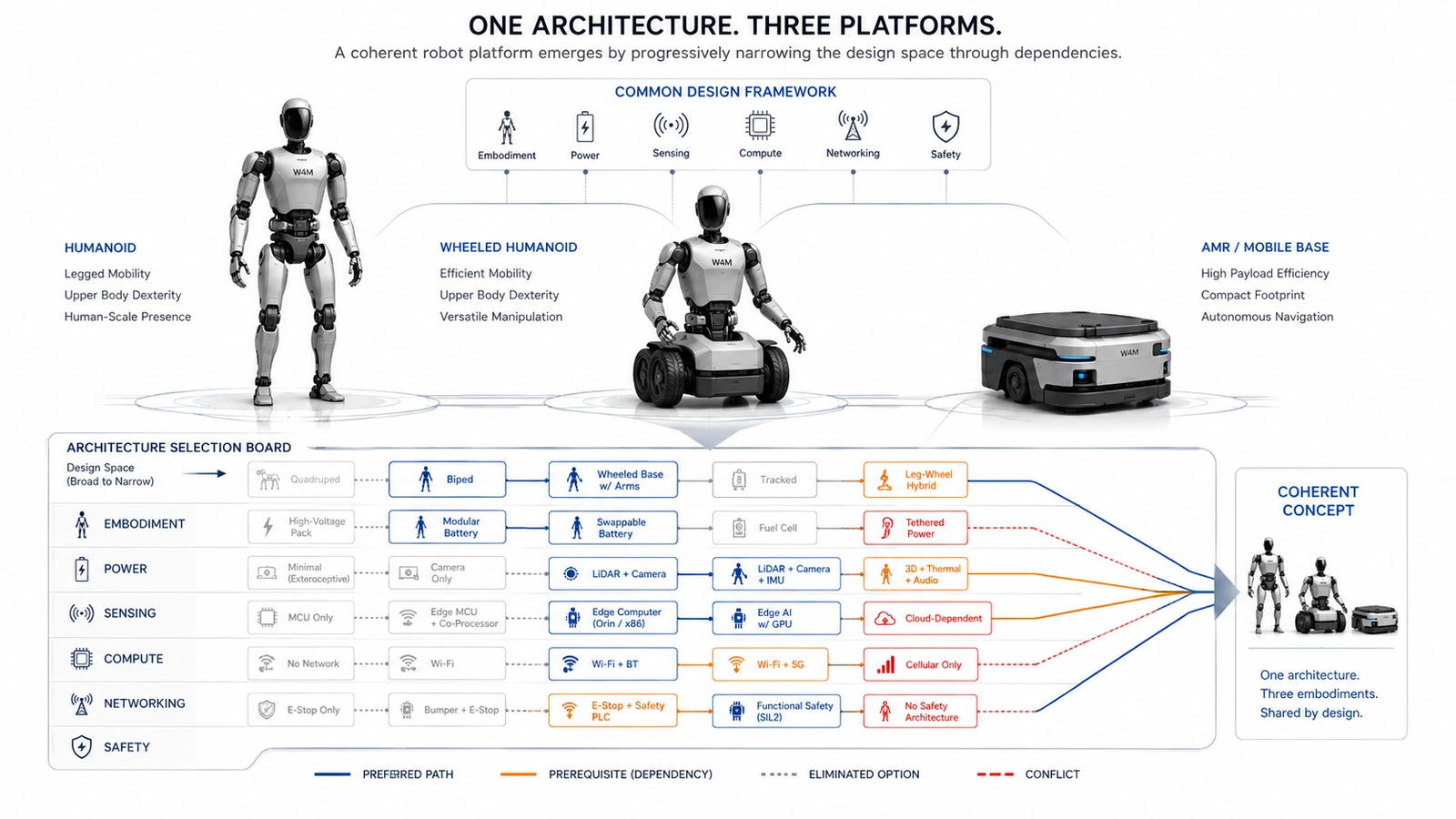
The Morphological Box Is a Starting Point, Not the Answer
Morphological analysis was developed to structure complex, multidimensional problem spaces whose important relationships cannot be reduced cleanly to one equation. Tom Ritchey describes General Morphological Analysis as a way to construct a conceptual problem space and then use cross-consistency assessment to identify coherent configurations. Ritchey
That logic fits robot platform architecture unusually well. A humanoid combines embodiment, mechanics, actuation, energy, sensing, compute, communication, safety, cybersecurity, thermal management, manufacturing and service. Each domain contains alternatives. A morphological box prevents the team from jumping directly from a requirement to a familiar part number and forces a more fundamental question: which solution principle should the system use?
| Architecture dimension | Representative solution principles |
|---|---|
| Embodiment | Biped humanoid; wheeled humanoid; quadruped; mobile manipulator; AMR |
| Transmission | Planetary; strain-wave; cycloidal; belt/cable; direct or quasi-direct drive |
| Energy storage | Central pack; distributed packs; swappable cartridges; buffered battery architecture |
| Compute | Distributed; zonal; centralized; hybrid central-plus-local |
| Motion communication | CAN FD; EtherCAT; Ethernet TSN; Single Pair Ethernet; mixed topology |
| Service strategy | Depot repair; subsystem replacement; joint modules; field-replaceable units |
The same logic appears in mainstream systems engineering. NASA describes early architecture work as the generation, analysis and ranking of alternatives, with less promising concepts dropped as the team proceeds to greater resolution. It also emphasizes that interfaces, maintainability, risk, technology maturity, cost and operations belong in the trade process, not after it. NASA Systems Engineering Handbook
The Design Space Is Not Rectangular
A conventional morphological table visually suggests that every option can be combined with every other option. Real robots do not work that way. Selecting an AMR makes leg kinematics and foot-contact sensing irrelevant. Selecting a biped activates balance, fall mitigation and legged-locomotion performance questions. ISO 18646-5:2026 now provides a current basis for specifying and evaluating locomotion performance of legged service robots, reinforcing that locomotion architecture should be connected to measurable complete-machine behavior. ISO 18646-5:2026
The same pattern repeats across electrical and electronic design. Selecting a 96 V motion bus affects conductor current, switch technology, pre-charge, protection, insulation and service handling. Selecting a sealed IP architecture constrains ordinary open-air cooling paths. Selecting a dexterous hand increases the relevance of tactile sensing, wrist perception, local processing and high-flex interconnects. Selecting fail-operational behavior changes the value of redundancy in compute, communication, sensing and power.
These relationships can be represented as architecture dependencies: directional IF→THEN statements whose meaning remains understandable without a solver. The distinction is important. Selecting high-voltage reinforced isolation does not imply that the robot must use a 96 V bus; selecting a 96 V bus, however, should trigger a deliberate isolation and protection review. Dependencies therefore have direction, severity and rationale.
Five Relationship Types Are Enough for a Practical Tool
A dependency-aware morphological box does not need hundreds of opaque equations. Five human-readable relationship types capture most useful architecture logic.
| Relationship | Meaning | Example |
|---|---|---|
| Not applicable | An upstream choice removes the need for a downstream dimension. | No arms → end-effector architecture becomes irrelevant. |
| Required | An upstream choice creates a prerequisite. | Higher-voltage bus → controlled pre-charge strategy required. |
| Recommended | A combination is not mandatory but is strongly preferred. | Dexterous hand → tactile sensing and close-range manipulation vision preferred. |
| Forbidden | A specific combination is architecturally inconsistent. | High IP target → ordinary open forced-air path conflicts unless specially isolated. |
| Review | The combination is feasible but needs quantitative engineering analysis. | Direct drive → verify motor torque, bus current and thermal margin. |
The safety analogy is useful. ISO 12100 treats machinery safety as a lifecycle process of identifying hazards, evaluating risk, reducing risk and documenting the result. A morphological dependency engine should not claim to certify safety, but it can make sure that safety consequences are pulled into the architecture discussion when relevant choices are made. ISO 12100:2010
Likewise, the rules should remain visible. A team should be able to read: IF motion bus = Ethernet TSN, THEN precise time synchronization is required or strongly preferred. IEEE defines Time-Sensitive Networking as deterministic IEEE 802 connectivity with bounded latency, controlled delay variation and low loss, and its standards family explicitly includes timing and synchronization mechanisms. IEEE 802.1 TSN
Guide the Architect; Do Not Replace the Architect
The most important usability principle is restraint. A configuration tool should not silently force a robot into an architecture merely because a rule table says so. Context matters. A seemingly unusual combination can be valid because of a customer interface, legacy actuator, infrastructure constraint, safety concept or supply-chain decision that sits outside the model.
A practical interface can therefore use four visible states. Grey means irrelevant or excluded. Blue means preferred. Orange means a prerequisite or engineering attention. Red means a conflict. The architect still selects the value explicitly, and a short explanation identifies the rule that produced the guidance. This keeps the model auditable and makes disagreement productive: engineers can challenge the dependency itself rather than reverse-engineering a formula.
This approach also separates validity from optimization. A 24 V dynamic humanoid may be technically possible, but current and copper losses could make it unattractive. That should trigger analysis rather than an automatic prohibition. In contrast, a direct contradiction between a selected interface and a mandatory prerequisite can justifiably be shown as a conflict. The tool becomes a structured conversation about engineering rationale.
Work From Core Decisions Toward Conditional Detail
Another source of complexity is treating every architecture row as equally urgent. It is more useful to distinguish three decision classes. Core decisions define the platform and should be addressed early. Conditional decisions become important only after an upstream choice activates them. Detailed decisions can remain open until the architecture is sufficiently mature.
Core decisions include embodiment, mobility, manipulation, environment, voltage class, actuator integration, energy architecture, sensing topology, compute topology, communication backbone and safety concept. Conditional decisions include battery-swap interfaces, safe-motion communication, optical de-fogging, redundant networks and module authentication. Detailed decisions include implementation refinements that do not need to be frozen before quantitative sizing.
This progressive approach is consistent with NASA's description of architecture development as an iterative process in which multiple concepts are generated, compared and refined before a baseline is selected. NASA
Modularity Makes Dependencies More Important
Modularity is not just a mechanical question. ISO 22166-1:2021 addresses modular frameworks, open modular design and module integration for service robots. ISO 22166-1:2021 ISO 22166-201:2024 adds a common information model intended to support interoperability, reusability and composability of modules. ISO 22166-201:2024 ISO 22166-202:2025 extends structured information to software modules, including interfaces, properties, composition and execution across lifecycle stages. ISO 22166-202:2025
That progression has an architectural consequence: choosing an open or third-party module ecosystem should activate more than a standardized bolt pattern. It should trigger decisions about electrical interfaces, software contracts, module identity, calibration ownership, compatibility metadata, cybersecurity and service diagnostics. A replaceable joint is not truly modular if swapping it requires undocumented calibration, bespoke wiring and manual firmware patching.
Dependency-aware morphology makes those hidden obligations visible. If the platform selects joint-level field replacement, the tool can recommend self-identifying modules, stored calibration data and serviceable connectors. If third-party modules are permitted, authenticated identity and version compatibility can become prerequisites. The model turns a marketing word such as modularity into a set of concrete system obligations.
Architecture Choices Reach the Semiconductor Layer Early
The semiconductor architecture appears before the bill of materials. A voltage-class choice already influences power switches, gate drivers, sensing, DC/DC conversion and protection. A distributed actuator architecture increases the number of local controllers, transceivers, position/current sensors and diagnostic nodes. A multi-modal perception architecture changes bandwidth, synchronization, memory and compute. A modular service strategy increases the value of nonvolatile identity, secure authentication and programmable protection.
Infineon's current humanoid portfolio presentation reflects this system coupling: motor control, sensing, battery and power management, communication, memory, functional-safety support and hardware security are presented as connected blocks of the robot architecture rather than isolated device categories. Infineon humanoid robotics
This is especially important for Physical AI. A physical machine cannot treat compute, motion and energy as separable abstractions. The AI planner may request motion, but the actuator, power network, communication path and safety architecture determine whether that motion can be executed within current limits and timing constraints. The morphological box therefore becomes a bridge from product requirements into semiconductor opportunity and system-level reference architectures.
Stop the Morphology Before It Becomes a Simulator
A common failure mode is to keep adding detail until the morphological box becomes an unmaintainable pseudo-simulation. The boundary should remain clear. The morphology chooses architecture principles; downstream models calculate quantitative values.
| Belongs in morphology | Belongs downstream |
|---|---|
| 48 V, 72 V or 96 V bus class | Peak bus current and conductor cross-section |
| Central, zonal or joint-integrated inverter | Exact MOSFET, gate driver and thermal sizing |
| Battery-only or battery-plus-supercapacitor | Required kWh, peak C-rate and runtime |
| Ethernet TSN or CAN FD architecture | Traffic schedule, utilization and worst-case latency |
| Passive, forced-air or liquid cooling | Thermal resistance, flow rate and junction temperature |
| Joint module or limb module service strategy | MTTR, spare inventory and service cost |
The handoff point is the architecture freeze. At that point the major solution principles and interfaces are coherent enough for mission-profile simulation, motor sizing, power-flow calculation, network analysis, thermal modeling, safety analysis and cost estimation to become meaningful. Architecture may still change, but quantitative models now operate on a deliberate concept rather than an accidental collection of subsystem defaults.
A Better Architecture Process
The resulting workflow is straightforward: requirements define the problem; morphology exposes the alternatives; dependencies progressively narrow the feasible design space; engineers preserve legitimate exceptions with rationale; a coherent concept is frozen; quantitative sizing and mission simulation then test whether the concept actually meets performance, energy, thermal, safety and cost targets.
The strongest version of this process remains transparent. The dependency catalogue is human-readable. The current configuration shows which rules are triggered. Preferred options are visible but not forced. Conflicts are explicit. References explain why the rules exist. Changes to a rule can be reviewed like any other engineering assumption.
Robot development will always require judgment because the design space spans disciplines and because new technologies continuously shift the trade-offs. The purpose of dependency-aware morphology is not to remove that judgment. It is to apply it earlier, more systematically and with better visibility across subsystem boundaries.
Good architecture is partly the art of eliminating bad combinations before they become expensive hardware. A robot platform should begin with a wide design space, but it should not stay wide. Every sound decision should make the next decision clearer.