
Abstract
Humanoid robots contain dozens of actuators, sensors and computing nodes whose internal data movement is continuous even when mechanical power is low. This study develops a first-principles communication-energy model for a representative 40-degree-of-freedom humanoid, compares EtherCAT, CAN-FD, switched Ethernet, 10BASE-T1S, hybrid and zonal architectures, and separates device evidence from engineering assumptions. The result is not a single universal watt figure. Depending on topology, node count, controller partitioning and power-state discipline, communication-related electronics can plausibly range from a few watts to several tens of watts. The decisive variable is not raw bit rate alone but how many PHYs, switch ports, slave controllers, clocks and gateways are kept awake, and where fast control loops are closed.
Internal Data Movement Is an Always-On Load
A humanoid can appear mechanically still while remaining electronically busy. Joint encoders continue to report position. Torque sensors and inertial measurement units update. Safety channels watch for faults. The real-time controller maintains state. Camera and perception subsystems may remain active. Network PHYs preserve links and timing. Gateways bridge domains whose traffic patterns differ by orders of magnitude. None of these functions produces visible motion, yet each draws electrical power.
This distinction matters because the largest actuator loads are intermittent. A dynamic gait or lift can draw hundreds of watts or more, while attentive idle can fall toward a few hundred watts or below. A network that consumes 10 W is therefore almost invisible during a 1 kW burst but becomes a material percentage of a 150–250 W low-load state. Communication energy is consequently best treated as a mission-integrated floor rather than as a fixed percentage of peak robot power.
The technical problem is also architectural. High-performance humanoids frequently use distributed joint controllers because local control reduces central processing burden and can improve fault containment. Peer-reviewed work on the HYDROïD electro-hydraulic humanoid describes a hierarchical, distributed EtherCAT architecture in which the embedded actuator layer is connected to a central real-time controller and the communication fieldbus constrains achievable update performance [1]. The paper establishes the feasibility and control value of distributed deterministic networking. It does not report a complete communication-energy budget, so no robot-level watt claim is inferred from it.
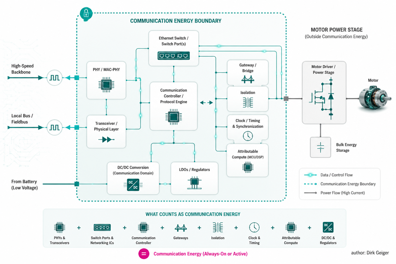
The relevant quantity is therefore broader than PHY power. For this study, communication-related power is defined as:
Pnetwork = ΣPPHY + ΣPswitch + ΣPcomm-controller + ΣPgateway + ΣPisolation + ΣPclock + Pattributable compute + Pconversion loss.
Motor-control computation that would exist even without the external network is excluded. Conversely, a processor block or peripheral clock that is required only to maintain communication belongs in the communication budget. This boundary is imperfect in highly integrated controllers, so estimates are reported as ranges and explicitly marked where the separation cannot be measured from public information.
The accompanying communication-energy boundary makes the accounting rule explicit: network power includes the electronics needed to move and time data, while the motor power stage and mechanical load remain outside the boundary.
Reference Humanoid and Communication Requirement Map
To make architecture comparisons repeatable, the calculations use a notional 40-DoF electric humanoid. It contains 40 intelligent actuator nodes, two hands with local sensing, six inertial or force-sensing clusters, a battery-management subsystem, a central real-time controller, an AI/perception computer and four high-bandwidth perception sensors. The reference configuration is an engineering model, not a claim about one commercial robot.
Three control time scales are separated. Fast current regulation is assumed to close inside the motor drive at approximately 10–40 kHz and therefore does not cross the body network. Joint torque, position or impedance commands cross the robot network at 500 Hz or 1 kHz. Supervisory telemetry, thermal data and diagnostics operate at tens of hertz or on demand. This partition follows the general direction visible in distributed humanoid control research: local controllers execute time-critical functions while a central controller coordinates the body [1].
| Domain | Nodes | Typical data | Update rate | Payload/node | Approx. payload bandwidth | Latency / sync need | Criticality | Candidate interfaces |
|---|---|---|---|---|---|---|---|---|
| Joint coordination | 40 | Command, position, velocity, torque, status | 1 kHz assumption | 64 B/cycle assumption | 20.48 Mbit/s one-way payload equivalent | <1 ms class, tight sync | High | EtherCAT, TSN Ethernet, segmented CAN-FD |
| Hands / tactile aggregation | 2 zones | Finger state, tactile features | 250 Hz assumption | 256 B/zone | 1.02 Mbit/s | Few ms | Medium-high | CAN-FD, 10BASE-T1S, Ethernet |
| IMU / force clusters | 6 | Acceleration, angular rate, wrench | 1 kHz assumption | 48 B | 2.30 Mbit/s | Sub-ms timestamp useful | High | SPI local, CAN-FD, Ethernet |
| BMS / power | 4 logical nodes | Voltage, current, temperature, faults | 10–100 Hz | 32 B | <0.1 Mbit/s | 10–100 ms | High for faults | CAN-FD, UART, SPE |
| Safety supervision | 6 zones | Heartbeat, safe-state variables | 100–1000 Hz | 16–32 B | <1.5 Mbit/s | Deterministic | Very high | Safety-over-EtherCAT, safety protocols over Ethernet, redundant CAN |
| Perception | 4 | Camera/LiDAR raw or compressed streams | Frame based | Architecture dependent | 100 Mbit/s to multi-Gbit/s | Timestamp critical | Medium-high | MIPI, GMSL, 1/2.5/10GbE |
| Diagnostics / update | All | Logs, firmware, traces | Burst | Variable | Low average, high burst | Non-real-time | Medium | Ethernet/IP, CAN-FD |
The 40-joint payload calculation deliberately excludes line coding, Ethernet framing, inter-frame gaps, protocol headers, synchronization traffic and retries. At 64 bytes × 8 × 1,000 × 40, the bare one-way payload is 20.48 Mbit/s. Bidirectional command and feedback of equal size would double that to 40.96 Mbit/s before overhead. That number immediately exposes a limitation of a single low-speed multidrop segment for the entire body. It does not imply that every joint needs a dedicated 100-Mbit/s link; it implies that segmentation, aggregation and frame design determine feasibility.
Component-Level Power Evidence
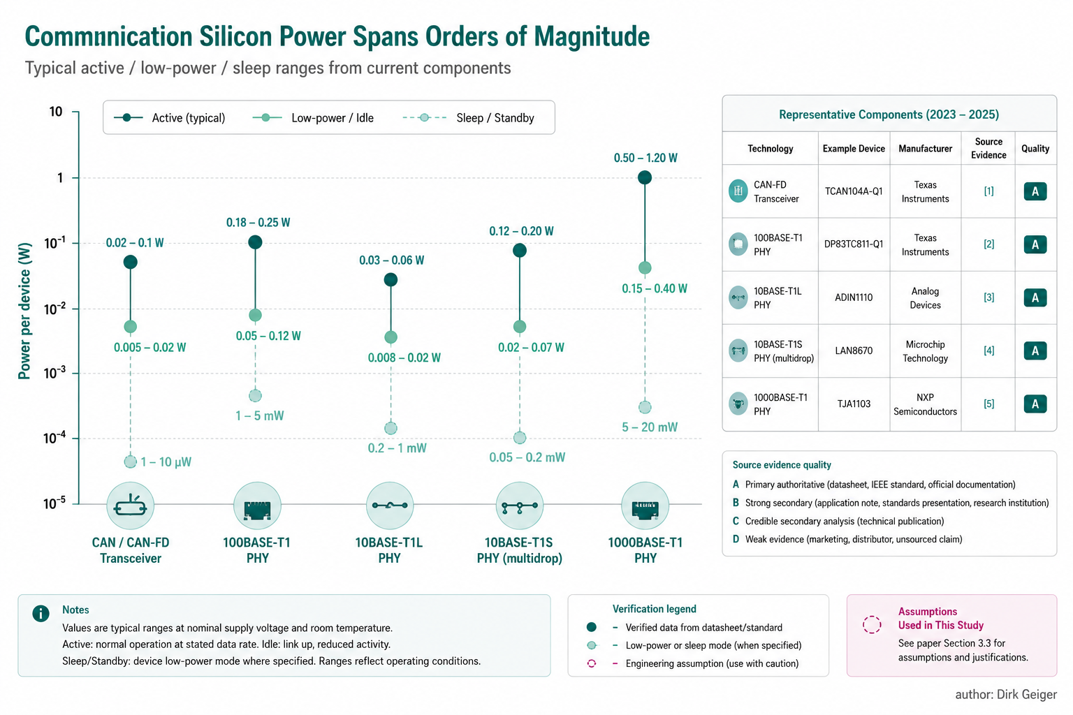
Published component data show a spread of more than an order of magnitude between different physical layers and operating modes. The comparison must be handled carefully because these products solve different problems and quote power under different conditions.
Texas Instruments specifies the DP83TC811S-Q1 100BASE-T1 automotive Ethernet PHY at less than 230 mW active and provides sleep, standby and disable modes [2]. NXP’s TJA1103 is a current 100BASE-T1 device supporting IEEE 1588/802.1AS timestamping and OPEN Alliance TC-10 sleep/wake functionality, illustrating that deterministic time distribution and network power management can coexist in one automotive-class PHY [3]. Analog Devices specifies 42 mW for the ADIN1110 10BASE-T1L MAC-PHY at its cited low-power operating point [4]. The number is relevant as evidence that 10-Mbit/s single-pair Ethernet can be implemented at very low power, although 10BASE-T1L is point-to-point and optimized for industrial long reach rather than as a direct substitute for 10BASE-T1S in a humanoid limb.
For CAN-FD, TI’s TCAN1044A-Q1 provides a useful bounded example. Its datasheet reports 95 mW typical average dissipation for a 250 kHz, 50% duty-cycle test and 120 mW under a higher-frequency/high-temperature condition; standby current is in the microampere range [5]. The same datasheet lists normal-mode recessive supply current in the single-digit milliampere range and dominant current in the tens of milliamperes. Therefore CAN transceiver power depends strongly on bus duty cycle, termination and traffic pattern. Treating CAN as a fixed “few milliwatts” is as misleading as treating it as permanently at worst-case dominant current.
Microchip’s LAN8670/1/2 family demonstrates automotive-qualified 10BASE-T1S for multidrop edge connectivity [6]. The current datasheet distinguishes silicon revisions: Rev C2 is listed at 129 mW typical normal-operation power, while Rev D0 is listed at 147 mW typical under the stated continuous-transmission conditions; both list 132 µW typical sleep power on the always-on supply when the other rails are removed [7]. The architecture calculations use 0.15 W/node as a rounded active T1S-class value. That number is therefore close to the Rev D0 device figure, but the complete node still requires a controller and local conversion whose power is accounted elsewhere.
EtherCAT requires a different accounting treatment. The LAN9252 is a two/three-port EtherCAT slave controller with dual integrated 100-Mbit/s Ethernet PHYs [8]. A joint using such a device is not comparable to one CAN transceiver or one single-port PHY: the EtherCAT device incorporates forwarding, distributed-clock and process-data functionality and can have two active line-side PHYs. Public humanoid implementations confirm that this class of slave controller is integrated directly into joint electronics [1]. Where a current product-specific power figure was not reliably extracted from a primary manufacturer page, this paper does not substitute a distributor estimate. Instead, the EtherCAT budget uses a 0.35–0.65 W/node communication-controller range, explicitly labeled as an engineering assumption to be validated on hardware.
| Technology | Representative device / evidence | Function | Active / normal power | Low-power evidence | Data rate | Evidence quality |
|---|---|---|---|---|---|---|
| CAN/CAN-FD | TI TCAN1044A-Q1 | CAN FD transceiver | 95 mW typical average in stated 250 kHz 50% test; 120 mW in stated high-temperature test [5] | Microamp-class standby current [5] | Up to 8 Mbit/s device capability | A |
| 100BASE-T1 | TI DP83TC811S-Q1 | Automotive SPE PHY | <230 mW active [2] | Sleep, standby, disable [2] | 100 Mbit/s | A |
| 100BASE-T1 | NXP TJA1103 | Automotive SPE PHY | Power not used numerically here | TC-10 sleep/wake; 1588/802.1AS timestamping [3] | 100 Mbit/s | A |
| 10BASE-T1L | ADI ADIN1110 | Low-power MAC-PHY | 42 mW at cited operating point [4] | Low-power architecture focus | 10 Mbit/s | A |
| 10BASE-T1S | Microchip LAN8670/1/2 | Automotive multidrop SPE PHY | 147 mW typical for Rev D0 under stated continuous-transmission conditions; 0.15 W/node used in model [7] | 132 µW typical sleep power on the always-on supply when switchable rails are removed [7] | 10 Mbit/s | A for device data; assumption for complete-node model |
| EtherCAT | Microchip LAN9252 class | Slave controller + dual PHYs | 0.35–0.65 W/node modeling range | Not modeled as deep-sleep capable in active chain | 100 Mbit/s line rate | A for architecture; assumption for power |
These data support two conclusions. First, protocol names are poor proxies for watts. A low-power 10-Mbit/s MAC-PHY can consume far less than a 100-Mbit/s automotive PHY, while a CAN transceiver can move from microamp standby to roughly 0.1 W-class average dissipation depending on activity. Second, topology multiplies device power. Forty 0.2 W endpoints already equal 8 W before the central-side PHYs, switching, clocks or conversion losses are counted.
The component-power comparison visualizes why a single protocol label is insufficient. Active values cluster in the tens to hundreds of milliwatts per device, while supported sleep states can fall by orders of magnitude; topology determines how many of those devices remain awake.
Seven E/E Architectures and Their Energy Consequences
Distributed EtherCAT to Most Joints
EtherCAT is technically compelling for deterministic multi-axis motion. A frame can pass through distributed slaves with synchronized clocks, and robotics research has demonstrated multi-kilohertz update rates in humanoid systems [1]. In a chain-oriented joint architecture, however, each intelligent joint carries communication silicon that remains active whenever the chain must be operational. The energy penalty is not Ethernet traffic itself but the number of always-on forwarding and slave-control circuits.
For a 40-joint model using 0.50 W/node as the midpoint of the assumed 0.35–0.65 W range, joint communication contributes 20 W. Add 1.5 W for master/interface electronics, 1.5 W for junctions and timing, and 2 W for conversion/isolation overhead, and the active communication budget reaches approximately 25 W. A lower-power implementation could fall below this number; a controller with heavier isolation and local processing could exceed it.
CAN-FD Distributed Control
CAN-FD minimizes physical-layer complexity and naturally supports multidrop wiring. If the 40 joints are divided across four to six buses, transceiver count remains one per node plus controllers at the zone or central side. Using 40 mW average per transceiver as a low-to-moderate traffic engineering assumption—not the 95 mW cited test point—40 joints contribute about 1.6 W. With six central transceivers, controller overhead, isolation and DC/DC losses, an active 3–5 W network is plausible.
The constraint is payload and scheduling. A single 8-Mbit/s CAN-FD bus cannot carry the 40.96 Mbit/s bidirectional bare payload assumed for all 40 joints at 1 kHz. Segmentation, smaller payloads, lower update rates or local aggregation are mandatory. CAN-FD therefore wins energy only when the control architecture is designed around its bandwidth envelope.
Flat Switched 100BASE-T1 Ethernet
A flat Ethernet topology gives every joint a dedicated switched link. If 40 edge PHYs consume 0.20 W each and 40 switch-side ports incur a similar PHY-equivalent cost, PHY power alone approaches 16 W. Switch fabric and controller overhead then lift total active network power into the 18–24 W range. This architecture offers abundant bandwidth and clean addressing, but it pays for bandwidth at every endpoint even when most joints carry only modest cyclic state.
Ethernet-TSN to the Edge
Time-Sensitive Networking improves scheduling, traffic shaping and synchronization on standards-based Ethernet. NXP’s TJA1103, for example, supports IEEE 1588v2/802.1AS timestamping and TC-10 sleep/wake capability [3]. TSN therefore addresses important determinism and power-state mechanisms. It does not, however, eliminate the endpoint-count problem. A TSN PHY at every joint still consumes power at every joint. The architecture becomes compelling when TSN is applied selectively to backbones and high-rate zones rather than reflexively to every sensor.
10BASE-T1S Multidrop at Suitable Edges
10BASE-T1S is architecturally attractive because multiple nodes can share one single-pair segment, eliminating dedicated switch ports for low-bandwidth edge devices. Microchip positions its automotive LAN8670/1/2 family specifically for bringing lower-speed devices into Ethernet [6]. In a humanoid, hands, tactile modules, thermal sensors, auxiliary actuators and some limb clusters are plausible candidates. The limitation is the 10-Mbit/s shared line rate. A full-body 40-joint 1-kHz network with the payload model in Table 1 is not feasible on one T1S segment; several short segments with aggregation are more credible.
Hybrid Ethernet Backbone Plus Local Buses
A hybrid architecture uses high-speed Ethernet only where its bandwidth and synchronization justify the cost. Six body zones—head, torso, left arm, right arm, left leg and right leg—connect to a central real-time controller through 100BASE-T1 or faster links. Inside each zone, CAN-FD, SPI, point-to-point serial links or T1S serve actuators and sensors. The key shift is that the high-power switched network sees six zones rather than 40 joints.
Zonal / Hierarchical Architecture with Local Fast Loops
The zonal version pushes the principle further. The fastest current and commutation loops remain entirely local. A limb controller aggregates encoder, torque, thermal and diagnostic data, performs consistency checks and exchanges state vectors with the central controller. High-rate raw data remain inside the limb whenever they are not required for whole-body control. Network rate can also follow robot state: 1 kHz during dynamic motion, 100–250 Hz during stable holding, tens of hertz for inactive appendages, and wake-only signaling during standby.
This architecture is not automatically superior. It introduces more capable zone controllers, software partitioning and local safety responsibilities. Yet it directly attacks the main energy multiplier: the number of continuously active high-bandwidth endpoints.
The architecture comparison shows the physical change that matters most for energy: moving from one high-capability communication endpoint per joint toward a small number of body zones with local edge buses. The number of joints does not disappear, but the number of continuously active high-speed backbone endpoints can stop scaling one-for-one with DoF.

Architecture Bills of Communication
The following bills use common modeling assumptions so that topology, rather than selective device choice, drives the comparison. Values are intentionally rounded. They represent communication-attributable electronics only and exclude AI compute, camera image sensors and motor-control power stages.
| Architecture | Dominant component assumption | Count / calculation | Subtotal | Other overhead | Estimated active total |
|---|---|---|---|---|---|
| EtherCAT to joints | 0.50 W/slave communication node | 40 × 0.50 W | 20.0 W | 5.0 W master, timing, isolation, conversion | 25 W |
| Segmented CAN-FD | 0.04 W average/node | 46 × 0.04 W | 1.84 W | 1.7 W controllers, isolation, conversion | 3.5 W |
| Flat 100BASE-T1 | 0.20 W/PHY endpoint | 80 endpoints × 0.20 W | 16.0 W | 4.0 W switch fabric, clocks, conversion | 20 W |
| Flat TSN Ethernet | 0.20 W/PHY endpoint | 80 endpoints × 0.20 W | 16.0 W | 5.0 W TSN switch/timing/overhead | 21 W |
| T1S segmented edge | 0.15 W/node assumption | 46 × 0.15 W | 6.9 W | 2.1 W controllers/bridges/conversion | 9 W |
| Hybrid zonal | 12 backbone PHY endpoints × 0.20 W + local buses | 2.4 W backbone + 2.0 W local edge | 4.4 W | 2.6 W zone-switch/timing/conversion | 7 W |
| Zonal + aggressive power management | Same physical topology, state-dependent | 7 W active baseline | 7.0 W | Reduced outside active state | 7 W active; lower mission average |
These estimates do not prove that EtherCAT necessarily consumes 25 W or CAN-FD necessarily consumes 3.5 W. They expose the architecture sensitivity. If a future EtherCAT slave solution consumes 0.20 W rather than 0.50 W, the 40-node subtotal falls by 12 W. If CAN traffic drives transceivers closer to the 95 mW dissipation point demonstrated by the TI datasheet test [5], the CAN network rises by several watts. The correct use of Table 3 is therefore as a parametric model.
Idle and standby states amplify architectural differences. A flat chain may need most nodes awake to preserve network continuity, whereas a star or zonal topology can selectively power-gate branches. A CAN node or Ethernet PHY with remote-wake functionality can enter very low-power states if the system architecture tolerates wake latency. NXP explicitly lists TC-10 sleep/wake support in TJA1103 [3], and TI lists sleep and standby modes for DP83TC811S-Q1 [2]. The semiconductor capability therefore exists; whether the robot uses it is a system-software decision.
Mission-Integrated Communication Energy
A four-hour reference mission is defined to expose the difference between active and average communication power: 60 minutes of dynamic work, 120 minutes of normal manipulation/walking, 60 minutes of attentive idle and 60 minutes of safe standby. The schedule is an engineering scenario, not a standardized humanoid mission.
For the conservative distributed-EtherCAT-style case, network power is assumed to be 25 W during dynamic work, 24 W during normal work, 20 W during attentive idle and 8 W during safe standby. The resulting communication energy is:
E = 25 W × 1 h + 24 W × 2 h + 20 W × 1 h + 8 W × 1 h = 101 Wh.
For the zonal architecture with active power management, assume 7 W dynamic, 6 W normal, 3 W attentive idle and 0.8 W safe standby:
E = 7 × 1 + 6 × 2 + 3 × 1 + 0.8 × 1 = 22.8 Wh.
The difference is 78.2 Wh over the four-hour mission. Against a 2 kWh battery, that is 3.91% of nominal pack energy. The number is large enough to matter, but it is not a guaranteed 3.91% runtime increase. A robot may stop for thermal limits, reserve-state constraints, safety margins or task scheduling before nominal pack depletion, and communications may share power rails with functions that cannot be gated independently.
| Architecture | Dynamic W | Normal W | Idle W | Standby W | 4 h mission Wh | Share of 2 kWh |
|---|---|---|---|---|---|---|
| EtherCAT distributed | 25 | 24 | 20 | 8 | 101 | 5.05% |
| Flat 100BASE-T1 | 20 | 19 | 15 | 3 | 76 | 3.80% |
| Segmented CAN-FD | 3.5 | 3.2 | 1.8 | 0.2 | 11.9 | 0.60% |
| T1S segmented | 9 | 8 | 4 | 0.6 | 29.6 | 1.48% |
| Hybrid zonal | 7 | 6.5 | 4 | 1.2 | 25.2 | 1.26% |
| Zonal + aggressive PM | 7 | 6 | 3 | 0.8 | 22.8 | 1.14% |
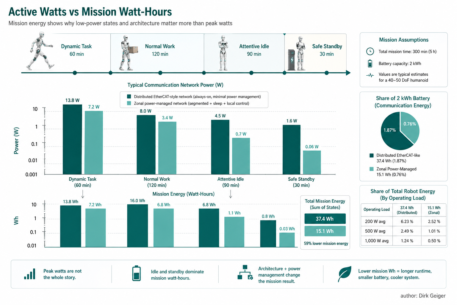
A second sensitivity case is useful because the 25 W distributed baseline deliberately sits near the upper half of the modeled range. The accompanying mission-energy visual therefore uses a lower-power five-hour scenario: 60 minutes dynamic, 120 minutes normal work, 90 minutes attentive idle and 30 minutes safe standby. Its distributed-network assumptions are 13.8, 8.0, 4.5 and 1.6 W across those states; the zonal power-managed assumptions are 7.2, 3.4, 0.7 and 0.06 W. These are scenario inputs, not measured robot values.
For that lower-power case, the distributed network consumes 37.35 Wh, rounded to 37.4 Wh, while the zonal power-managed network consumes 15.08 Wh, rounded to 15.1 Wh. The modeled reduction is approximately 59.6%. The two mission cases are intentionally not merged: the four-hour calculation tests a conservative topology penalty, while the five-hour visual tests whether architecture and sleep discipline still matter after the distributed baseline is pushed downward. They do.
The more revealing metric is network share of instantaneous robot power. A 20 W communication load is 2% of a 1 kW dynamic electrical load, 4% of a 500 W normal workload and 10% of a 200 W attentive-idle load. The same network therefore changes importance as the robot changes state. A 6 W network contributes 0.6%, 1.2% and 3% under the same three robot loads. Communication energy is consequently most exposed in low-load states, where actuator power falls but clocks, links, safety supervision and wake-capable domains may remain active.
The mission comparison also reveals a design trap. Optimizing only the peak network state can produce a device-level improvement that barely moves daily energy. A 1 W reduction maintained for five hours saves 5 Wh. Power-gating 10 W of unnecessary communication electronics during two hours of idle saves 20 Wh. The practical target is therefore not the minimum active watt figure in isolation, but the minimum state-weighted energy consistent with wake latency, synchronization recovery and safety.
Sensitivity to DoF, Update Rate and PHY Power
Node count is the strongest first-order multiplier in flat architectures. If the communication electronics attached to each joint draw 0.50 W, moving from 30 to 60 DoF adds 15 W of active network power before central overhead. In a six-zone architecture, the backbone PHY count can remain nearly constant as joints are added within existing zones, so network power rises mainly through local-bus nodes and zone-controller load.
| DoF / nodes | 0.05 W/node | 0.15 W/node | 0.20 W/node | 0.50 W/node |
|---|---|---|---|---|
| 30 | 1.5 W | 4.5 W | 6.0 W | 15 W |
| 40 | 2.0 W | 6.0 W | 8.0 W | 20 W |
| 50 | 2.5 W | 7.5 W | 10.0 W | 25 W |
| 60 | 3.0 W | 9.0 W | 12.0 W | 30 W |
Update rate has a subtler effect. For many Ethernet PHYs, active link power is weakly dependent on offered load compared with the cost of keeping the PHY synchronized. Dropping application traffic from 1 kHz to 500 Hz may therefore save little unless the change allows the link, MAC, switch port or processor to enter a lower-power state. CAN is more traffic-dependent because bus dominant/recessive duty cycle changes transceiver dissipation. The important design objective is thus not simply “send half as many frames,” but “use the lower traffic level to shut down clocks, reduce link rate or enter sleep.”
Payload scaling matters in the opposite direction. At 40 joints, reducing bidirectional joint state from 64 bytes each way to 24 bytes each way lowers bare payload from 40.96 Mbit/s to 15.36 Mbit/s. That can change the feasible topology: more joints fit on a shared segment, and aggregation becomes easier. Feature extraction at the edge is therefore an energy lever even when the PHY itself consumes similar active power.
The 5–30 W hypothesis survives sensitivity testing as a plausible envelope for communication-related electronics in a modern humanoid, but not as a universal measurement. Low-power CAN-based or strongly hierarchical designs can fall below 5 W. A 60-DoF robot with relatively power-hungry per-joint communication devices can exceed 30 W. The defensible statement is that topology can move communication power by several-fold at the same mechanical DoF.
Power-State Management Is the Highest-Leverage Optimization
Semiconductor efficiency improvements are useful, but mission energy is often dominated by how long devices remain in each mode. A reduction from 230 mW to 180 mW active saves 50 mW per PHY. Across 20 PHYs this is 1 W. By contrast, moving 20 PHYs from 200 mW active to a sub-10-mW sleep state during one hour of idle can save several watt-hours in a single hour. The exact saving depends on wake behavior and implementation, but the order-of-magnitude difference explains why robot-level state management can outrank incremental active-mode optimization.
Four mechanisms are particularly important.
First, network segmentation. A physically separable arm or hand should be able to enter a reduced-power communication state without breaking the timing chain of the rest of the robot. Daisy-chain architectures must be examined carefully because an intermediate powered-down node can disrupt downstream connectivity unless bypass mechanisms exist.
Second, local loop closure. Current and commutation loops belong inside the actuator drive. High-rate encoder data that are required only for those loops should not traverse the body network. Whole-body control should exchange torque, position, velocity, impedance, confidence and fault state at the rate actually needed for coordination.
Third, adaptive publication. A joint undergoing dynamic contact may warrant 1 kHz state updates, while a locked finger in an inactive hand may need only heartbeat and fault monitoring. Event-triggered messages for temperature, voltage drift or diagnostics can replace periodic telemetry when system safety permits.
Fourth, wake-capable physical layers. TJA1103 explicitly supports OPEN Alliance TC-10 sleep/wake [3], while DP83TC811S-Q1 lists sleep, standby and Wake-on-LAN functions [2]. CAN-FD transceivers such as TCAN1044A-Q1 support low-power standby and remote wake behavior [5]. These capabilities allow a robot to retain a small always-on supervisory domain while power-gating most of the communication fabric.
Those capabilities only save energy if the robot owns a coherent network state machine. A limb cannot be powered down merely because command traffic stops. The controller must first establish a mechanically safe state, define which sensors continue to supervise the limb, retain a wake path, bound wake latency, restore time synchronization, detect stale state and requalify the node before torque authority returns. The energy mechanism is therefore inseparable from control and safety architecture.
A useful implementation target is to specify communication behavior alongside each robot energy state. Full Active permits all high-rate links and diagnostic traffic. Task Active keeps only participating zones at full bandwidth. Attentive Idle preserves safety, time and wake supervision while inactive zones move to reduced-rate or low-power modes. Safe Standby retains only the minimum network needed to maintain a safe machine and accept an authorized wake request. Deep Sleep removes switchable communication rails except explicitly defined always-on wake circuitry. Measuring the transition energy and resynchronization time between these states is as important as measuring their steady-state watts.
| Improvement | Baseline | Improved | Indicative saving | Mission benefit | Difficulty | Technical risk / trade-off |
|---|---|---|---|---|---|---|
| Replace flat high-speed edge links with 6-zone backbone | 20 W flat Ethernet | 7 W hybrid zonal | 13 W active | ~52 Wh over 4 active hours | Medium-high | Zone controller complexity |
| Sleep inactive limbs in attentive idle | 7 W zonal | 3 W idle | 4 W during idle | 4 Wh per idle hour | Medium | Wake latency, safety supervision |
| Localize fast current loops | High-rate raw exchange | State-vector exchange | Topology-dependent | May enable slower/lower-power links | Medium | More local control responsibility |
| Adaptive update rates | 1 kHz all nodes | 1 kHz active / 100 Hz inactive | Small if PHY stays active; large if clock/link states change | Architecture dependent | Medium | Control observability |
| Multidrop edge networks | Dedicated switched ports | T1S/CAN shared segment | Eliminates switch-side PHYs/ports | Several watts possible at scale | Medium | Shared bandwidth and fault containment |
Architecture Scorecard
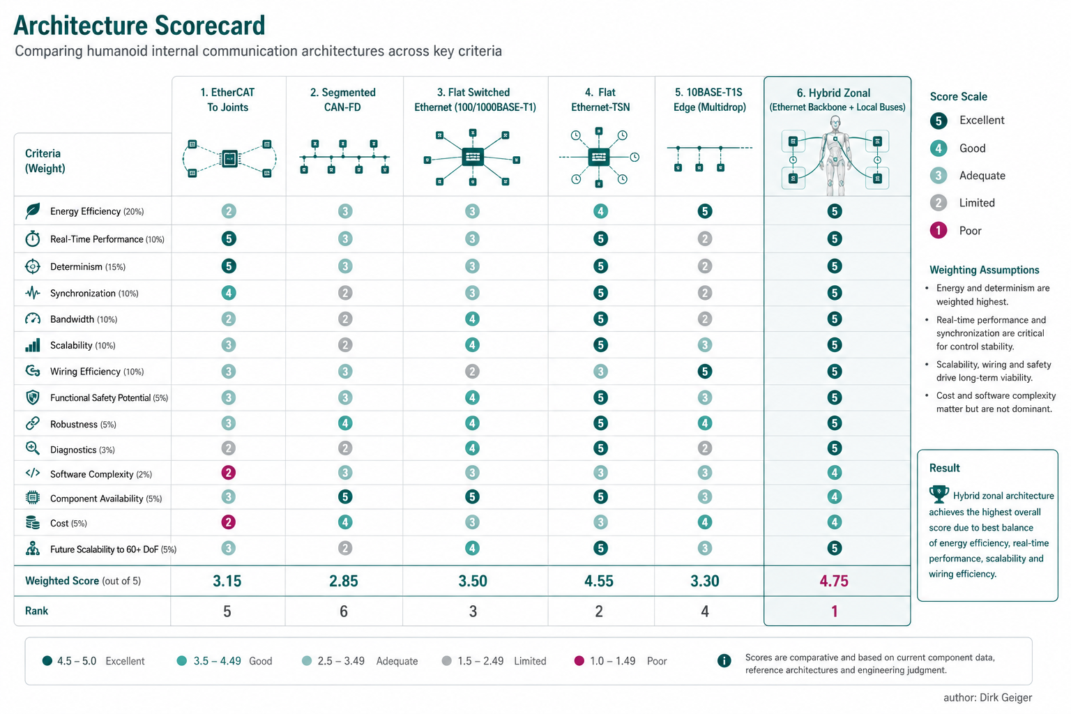
A final decision cannot be based on energy alone. The scorecard weights energy efficiency 15%, real-time performance 10%, determinism 8%, synchronization 8%, bandwidth 8%, scalability 10%, wiring efficiency 8%, functional-safety potential 7%, robustness 6%, diagnostics 5%, software complexity 5%, component availability 4%, cost 3% and scalability beyond 60 DoF 3%. Scores run from 1 (weak) to 5 (strong). The weights are engineering judgments and should be adjusted for a specific product program.
| Architecture | Energy | Real-time | Determinism | Sync | Bandwidth | Scalability | Wiring | Safety | Robustness | Diagnostics | Software simplicity | Availability | Cost | 60+ DoF | Weighted /5 |
|---|---|---|---|---|---|---|---|---|---|---|---|---|---|---|---|
| EtherCAT to joints | 2 | 5 | 5 | 5 | 4 | 4 | 3 | 4 | 4 | 4 | 4 | 5 | 3 | 4 | 3.91 |
| Segmented CAN-FD | 5 | 3 | 4 | 3 | 2 | 3 | 5 | 4 | 5 | 4 | 4 | 5 | 5 | 2 | 3.90 |
| Flat 100BASE-T1 | 2 | 4 | 3 | 4 | 5 | 4 | 2 | 4 | 4 | 5 | 4 | 5 | 2 | 4 | 3.55 |
| Flat TSN Ethernet | 2 | 5 | 5 | 5 | 5 | 5 | 2 | 5 | 4 | 5 | 2 | 4 | 2 | 5 | 4.10 |
| T1S edge dominant | 4 | 3 | 3 | 3 | 2 | 3 | 5 | 3 | 4 | 4 | 3 | 3 | 4 | 2 | 3.38 |
| Hybrid zonal | 5 | 5 | 5 | 5 | 5 | 5 | 5 | 5 | 4 | 5 | 2 | 4 | 3 | 5 | 4.67 |
The zonal architecture wins this weighting because it preserves high-performance Ethernet where the system needs bandwidth and timing while allowing lower-power buses at the edge. Its principal penalty is software and partitioning complexity. That penalty is real: zone controllers become architectural safety boundaries, and local state aggregation can conceal raw information that might otherwise aid central diagnostics. A poorly engineered zonal design can therefore be worse than a simpler flat system.
The scorecard should be read as a decision aid rather than a protocol ranking. Its value is the visibility of trade-offs: the highest-energy score is irrelevant if timing, fault containment or serviceability become unacceptable, and the highest-performance topology is unattractive if it forces unnecessary electronics to remain awake across the entire body.
Stress-Testing the Six Hypotheses
H1: Communication consumes approximately 5–30 W in a modern humanoid. The range is plausible but incomplete. A low-power, segmented CAN architecture can fall below 5 W, while 60 distributed high-power communication nodes can exceed 30 W. The useful conclusion is a broader engineering envelope of roughly 3–30+ W for the network electronics considered here, with 5–20 W a credible design region for many mixed architectures.
H2: A flat network with a PHY or communication controller at every joint creates unnecessary always-on power. Supported in principle. Flat architectures multiply active endpoints with DoF. Whether that power is “unnecessary” depends on latency, diagnostics, safety and modularity requirements. Dedicated links may be justified for high-dynamic joints or safety-critical modules.
H3: A zonal architecture can materially reduce communication energy. Supported by topology arithmetic, not yet by humanoid-specific fleet measurements. Reducing high-speed backbone endpoints from 40 to six zones cuts the dominant PHY/switch-port multiplier. The gain depends on what replaces the local links.
H4: Closing fast motor-control loops locally reduces both network load and system energy. Network-load reduction is strongly supported by information-flow logic and by distributed control practice. Total system-energy reduction is conditional: local computation consumes power, so the architecture saves energy only if avoided network and central-compute power exceed the added local processing cost.
H5: Sleep and dynamic network-rate management matter more to mission energy than incremental active-PHY efficiency. Usually supported when robots spend meaningful time at idle or standby. A 50 mW active-PHY improvement across 20 devices saves 1 W continuously. Putting those same devices into a much lower-power state for long intervals can save several times more. In a robot that operates continuously at maximum dynamic load, the balance shifts toward active efficiency.
H6: Communication matters proportionally more during idle than during dynamic motion. Supported mathematically. The same 10 W network is 1% of a 1 kW robot state and 5% of a 200 W state. This is a ratio effect even if network power itself is unchanged.
Recommended Humanoid E/E Architecture
The preferred architecture is hierarchical rather than doctrinaire. A high-speed Ethernet/TSN backbone should connect central real-time compute with a small number of body zones. Perception links should remain on interfaces appropriate to their bandwidth, including MIPI, serializer/deserializer links or Gigabit Ethernet where needed. Arms, legs, hands and torso should use local buses selected by control requirement rather than by a single robot-wide protocol mandate.
Within a limb, high-dynamic joints that require tightly synchronized state exchange may justify 100BASE-T1, EtherCAT-compatible local islands or deterministic Ethernet. Lower-bandwidth devices—thermal sensors, auxiliary actuators, BMS functions, tactile aggregators and some hand functions—can use CAN-FD or multidrop SPE. The zone controller should provide time translation, health aggregation and traffic policing, but it should not become a single unprotected point of failure.
The control partition should be explicit. Current loops stay in the inverter or actuator controller. Joint-level torque/position/impedance control stays local when feasible. Whole-body control exchanges physically meaningful state and intent. Perception compute transports features or synchronized frames according to algorithmic need rather than by default streaming every internal signal across the same network.
Power management should be treated as part of the network specification. Each communication domain needs defined Full Active, Task Active, Attentive Idle, Safe Standby and Deep Sleep behavior. Wake sources, wake latency, clock resynchronization, stale-data handling and safety requalification after wake must be designed rather than added later.
A practical starting point for a 40–60 DoF platform is six to eight zones rather than forty to sixty backbone endpoints. Head and torso zones carry perception, timing and power-management traffic; each arm and leg receives a dedicated zone; dexterous hands can become sub-zones when tactile bandwidth or serviceability justifies it. The backbone should expose enough bandwidth and deterministic timing for whole-body coordination, while the local network inside a limb is selected from the actual information rate, fault-containment need and wake behavior of its devices.
This architecture does not require eliminating EtherCAT, CAN-FD or T1S. It gives each technology a narrower job. EtherCAT remains attractive where a chain of tightly synchronized actuators benefits from its distributed control model. CAN-FD remains attractive for robust low-bandwidth control and safety-related support functions. T1S becomes useful where Ethernet semantics and multidrop wiring are valuable at the edge. Switched 100BASE-T1 or faster Ethernet carries aggregated zone traffic and time. The design objective is not protocol uniformity; it is minimizing unnecessary continuously powered communication capability while preserving deterministic control.
Fault containment must be designed with the same discipline as energy. A zone controller that aggregates eight joints can reduce endpoint and wiring overhead, but a single failure must not silently remove an entire limb from safety supervision. Redundant wake paths, independent safety islands, bypass capability or degraded-mode operation may add watts. Those watts are justified when they protect a required safety property. Energy optimization begins after the safety architecture is defined, not before it.
What Must Be Measured on Real Humanoids
Public evidence is strong on protocol capability and individual semiconductor behavior but weak on complete humanoid communication energy. The next step is therefore measurement, not more protocol debate.
A useful validation campaign should instrument the low-voltage rails feeding communication electronics independently from motor-control and AI compute rails. At least five states should be measured: powered but stationary, attentive idle, low-speed manipulation, dynamic walking and safe standby. For each state, log network traffic, PHY/link mode, switch-port utilization, controller clock states and rail power at millisecond resolution.
One limb should then be tested under controlled architecture substitutions: full-rate 1 kHz cyclic communication, 500 Hz cyclic communication, adaptive update, event-driven telemetry and power-gated idle. If the controller permits it, compare a dedicated point-to-point link with a shared local bus while holding the mechanical task constant. The critical output is not only average watts but energy per standardized mission segment.
Thermal effects should also be recorded. Ten watts dissipated across dozens of small joint electronics can be more problematic than ten watts dissipated centrally because it increases local enclosure temperature and may force heavier heat spreading. Wiring mass and connector count should be included in the comparison; communication architecture affects robot energy indirectly through mass, packaging and reliability.
Finally, network failures must be injected. A design that saves 5 W but cannot isolate a failed limb, preserve safe timing or recover deterministically does not improve the robot. Energy efficiency belongs inside a multi-objective architecture that includes safety, real-time performance, availability and maintainability.
Evidence Quality, Uncertainty and Design Boundaries
The largest uncertainty in this analysis is not the existence of communication power but its allocation. Modern joint electronics integrate motor control, sensor acquisition, safety monitoring and network functions on the same MCU or system-on-chip. A current measurement at the board connector therefore captures the whole controller, while a datasheet power number usually captures one semiconductor under a specific test condition. Without rail-level instrumentation or clock-domain power telemetry, the communication-attributable fraction cannot be separated precisely.
This matters most when comparing a distributed EtherCAT controller with a CAN transceiver. The EtherCAT device may integrate two PHYs, distributed clocks, frame forwarding and process memory. A CAN transceiver is only a physical-layer device and relies on the MCU for protocol handling. Comparing 0.5 W for a complete EtherCAT communication controller with 0.05 W for a CAN transceiver overstates CAN's advantage if the additional MCU workload required by CAN is omitted. The architecture budgets therefore include a generic controller/overhead allowance rather than presenting component figures as direct apples-to-apples comparisons.
The second uncertainty is operating mode. Manufacturer active-power specifications are often measured under defined traffic, load and supply conditions. TI's CAN-FD evidence illustrates the point: average dissipation changes with test frequency, duty cycle, bus termination and temperature [5]. Ethernet PHY active power can be less sensitive to traffic because significant power is spent maintaining the link, equalization and clock recovery. A realistic robot model therefore needs state occupancy as well as data rate. It is entirely possible for a nominally higher-bandwidth Ethernet link to consume less mission energy than a lower-bandwidth alternative if the Ethernet implementation enters sleep aggressively while the other network remains continuously active.
The third uncertainty is the power cost of synchronization. High-performance humanoids require coherent timing across joint, inertial and perception data. Distributed-clock support is one reason EtherCAT is attractive, and modern 100BASE-T1 devices such as TJA1103 expose IEEE 1588/802.1AS timestamping [3]. Clock trees, oscillators and timestamp engines consume power, but the alternative—poor synchronization—can force larger control margins, higher update rates or duplicated sensing. Those indirect energy costs are not captured in the network watt budget. A network that costs one additional watt but permits more stable control and lower actuator losses could reduce total robot energy.
The fourth boundary is functional safety. Safety communication is not simply another data stream. A humanoid that can produce substantial force around people requires bounded fault detection, controlled transitions and deterministic recovery. Redundant networks, independent wake paths or safety islands can increase communication power. Removing them for energy reasons would be a false optimization. The recommended zonal architecture therefore assumes that safety supervision remains powered and that zones can enter reduced-power states only after the system has established a safe mechanical condition.
The fifth boundary is wiring. A communication network has embodied electrical consequences beyond the silicon. Dedicated point-to-point links require more conductors, connectors and switch ports than multidrop networks. Extra cable mass increases the energy required to accelerate limbs, especially when conductors are routed distally. Connector count also affects packaging volume and failure probability. Conversely, a shared bus can make fault isolation harder. A broken or shorted segment may disable multiple actuators, requiring extra switches or redundant paths that consume additional power. These effects are architecture-dependent and should be added to a full humanoid energy model rather than hidden inside a generic network-efficiency number.
Perception interfaces form a separate category. High-resolution camera links can move orders of magnitude more data than joint-state networks, yet the interface power is tightly coupled to the camera, serializer, deserializer and AI compute pipeline. Assigning all of that power to "communication" would distort the comparison between motion-control architectures. The preferred accounting method is therefore to maintain two sub-budgets: deterministic control communication and perception/data-movement infrastructure. The latter includes camera serializers, high-speed Ethernet or MIPI interfaces, memory movement and network-interface activity in the AI processor. In advanced robots, data movement inside the compute subsystem may eventually exceed the external control-network power considered here.
A final uncertainty is technology generation. The semiconductor examples span devices optimized for automotive and industrial networking. Future highly integrated microcontrollers can incorporate TSN-capable Ethernet, CAN-FD and safety accelerators with lower incremental power than today's discrete implementations. That favors flexible architectural conclusions over fixed watt claims. The durable principles are to minimize unnecessary active endpoints, match link capability to information need, localize the fastest loops, preserve deterministic timing and make power state a first-class network requirement.
For engineering decisions, the evidence can therefore be ranked in three layers. Primary manufacturer and peer-reviewed sources establish protocol capability, operating modes and component behavior. Topology arithmetic establishes how device count multiplies power. Mission-level values remain modeled until measured on complete humanoids. The resulting numbers are useful for design exploration precisely because their assumptions are visible; they should not be quoted as measured consumption of a named commercial robot.
Conclusion
Internal data movement is neither free nor likely to dominate the energy budget of a working humanoid. For the reference model, communication-related electronics occupy a plausible engineering envelope from roughly 3 W for a carefully segmented low-power network to 25–30 W or more for highly distributed architectures with substantial always-on communication electronics. The envelope is a model, not a measurement of a commercial robot.
The decisive variable is architecture. Energy scales with active endpoint count, switch ports, communication controllers, gateways and supporting clocks more strongly than with payload alone. A 100-Mbit/s link maintained at every joint can consume more system energy than a shared lower-power edge network even when traffic is light. Conversely, a low-speed bus becomes infeasible if the control partition forces tens of megabits per second of cyclic body-state traffic through it.
A hierarchical E/E architecture provides the strongest balance found here: Ethernet/TSN for a small high-performance backbone, deterministic local buses for limbs and sensors, fast motor loops closed locally, and state-dependent network power management. In the conservative four-hour scenario, modeled communication energy falls from 101 Wh for the distributed EtherCAT-style case to 22.8 Wh for the aggressively power-managed zonal case. In the separate lower-power five-hour sensitivity case used by the mission visual, the corresponding values are 37.4 Wh and 15.1 Wh. Different assumptions produce different absolute numbers, but both cases expose the same mechanism: endpoint count and time spent awake dominate mission energy.
The remaining uncertainty is measurable. Instrument communication rails independently from motor and compute rails; log link states and switch-port activity; correlate traffic with robot mission state; and measure wake, synchronization and requalification transients. Until those data exist, claims about a humanoid network consuming a specific number of watts should remain bounded engineering estimates.
The practical answer is therefore conditional but actionable. Internal communication is likely to cost a few watts in an aggressively optimized architecture and several tens of watts in an endpoint-heavy one. The architecture that minimizes that cost without sacrificing real-time behavior is not a single protocol. It is a zonal hierarchy that reserves high-capability deterministic Ethernet for traffic that needs it, keeps fast control local, uses lower-power shared links at the edge, and allows inactive communication domains to become genuinely inactive.